The PSU firmware can be compiled and executed on a Windows, Linux or OS X system. The software simulator is a terminal application that can respond to any currently supported SCPI command described in this document. SCPI commands could be entered directly in the simulator’s terminal window (Fig. 1) or remotely by using the e.g. a Telnet client (Fig. 2).
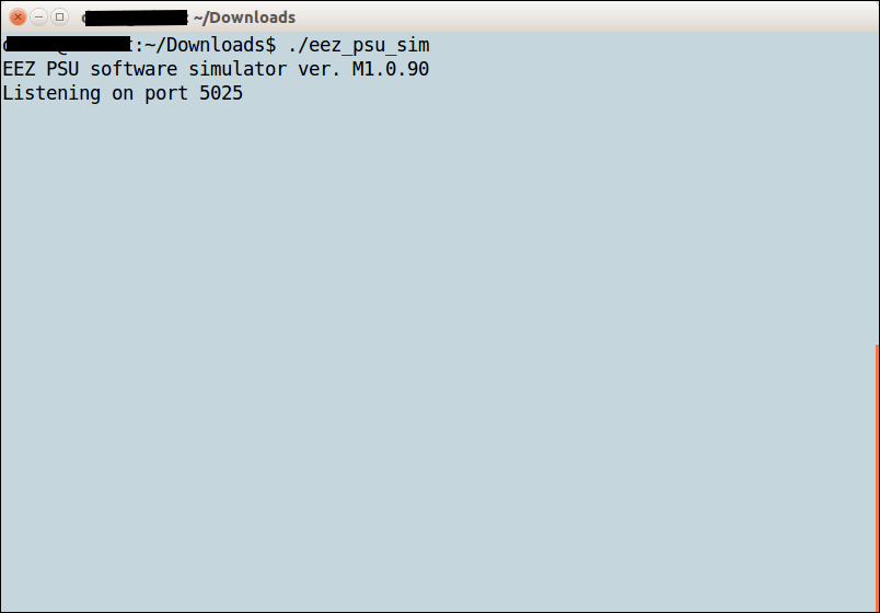
Fig. 1: Simulator welcome screen
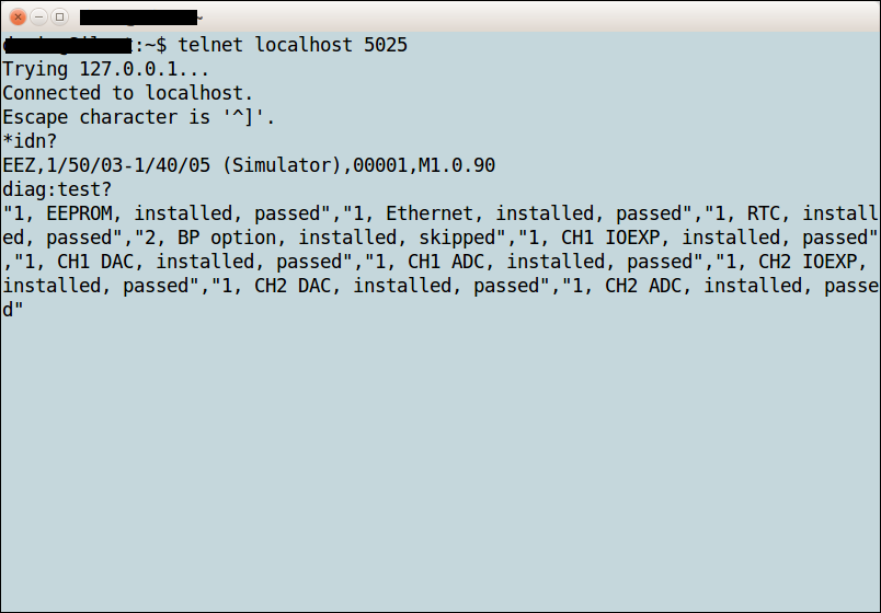
Fig. 2: Remote connection using a telnet client
The simulator also has an internal GUI. When started, open a separate window with the picture of the PSU front panel. The GUI depends of which PSU revision is used that can be set in conf_user_revision.h file before simulator compilation.
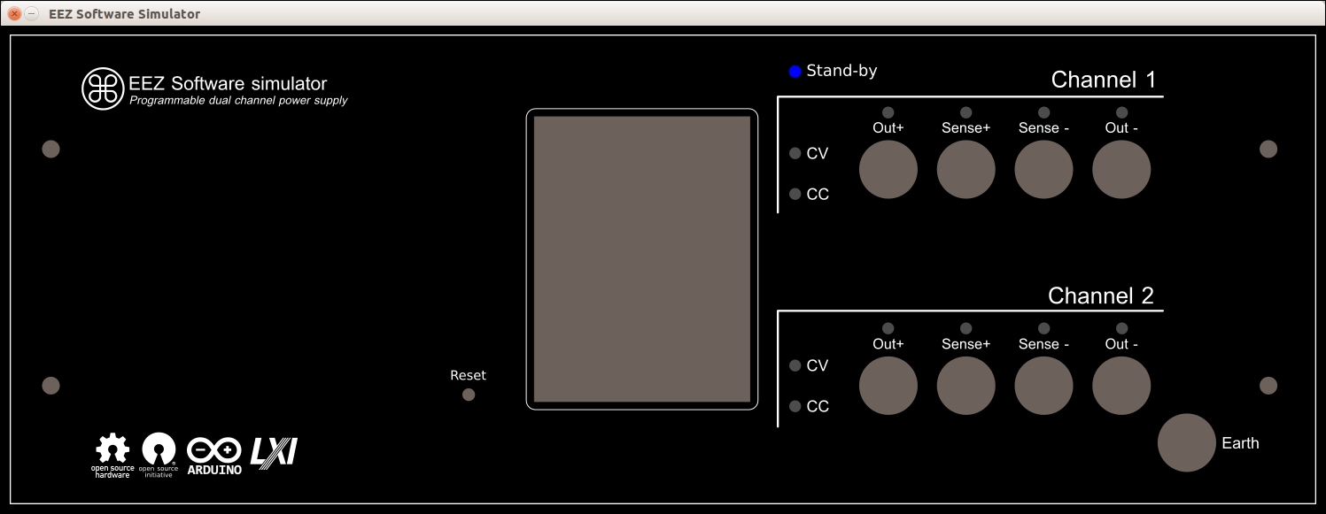
Fig. 3: Simulator GUI for portrait front panel (r1B9)
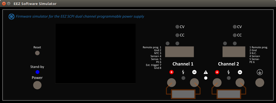
Fig. 4: Simulator GUI for landscape front panel (r3B4)
The GUI simulator front panel currently displays only changes in LED indicators and indicates whether load is applied on the output terminals or not. For example if an 8.2 Ohm load is connected to channel 2 and causes that channel to enter CC mode, the GUI front panel will indicate that in the following way:
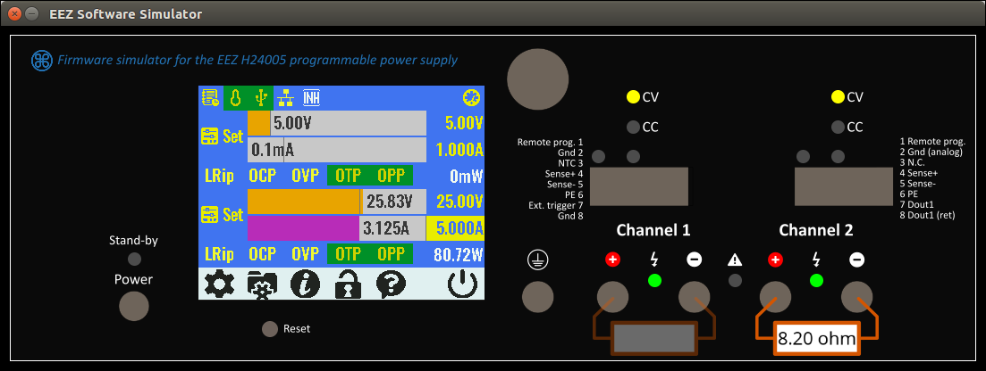
Fig. 5: Simulator GUI with a connected load on channel 2 (r5B12)
9.1. SIMUlator
The SIMUlator software subsystem implements a set of unclassified SCPI commands for managing external parameters and events such as load impedance, connection and disconnection of the load, sensor temperature or the PSU control circuit power supply state. Thus it is possible to exercise the measuring and protection commands that depend on external events.
For example, a MEASure:CURRent? command without a connected load will always return zero, or activation of the VOLTage:PROTection:STATe will automatically trip the OVP signal since a channel in CC operation cannot start when output is switched on, etc.
|
SCPI command |
Description |
|
SIMUlator |
|
|
Closes simulator |
|
|
Starts simulator’s GUI |
|
|
Sets the value of the simulated load |
|
|
“Connects” a simulated load to the channel output |
|
|
Sets the value of the PIN1 input |
|
|
Sets the PWRGOOD signal state |
|
|
Closes simulator |
|
|
Sets the RPOL signal |
|
|
Sets the temperature sensor value |
|
|
Sets the output voltage when a channel is in external programming mode |
|
Syntax |
SIMUlator:EXIT |
|
Description |
This command close all Simulator windows (terminal and GUI if started). |
|
Usage example |
SIMU:EXIT |
|
Syntax |
SIMUlator:GUI |
|
Description |
This command starts the GUI simulation in a new window (see Fig. 3 and Fig. 4). |
|
Usage example |
SIMU:GUI |
|
Related Commands |
SIMUlator:EXIT
|
|
Syntax |
SIMUlator:LOAD {<resistance>} SIMUlator:LOAD? |
|||
|
Description |
This command define the impedance of a simulated load connected to a channel output. Units are in ohms. With a load connected it is possible to simulate several PSU operations: e.g., CC mode of operation, current and power measurement, OCP and OPP functionality, etc.
The simulated load value can be also changed by clicking and dragging the load’s image. Move to the left to decrease, or to the right to increase the simulated value in increments of 1 Ω.
The simulator currently cannot emulate the “UR” mode of operation (see the OUTPut:MODE? command). |
|||
|
Parameters |
Name |
Type |
Range |
Default |
|
<resistance> |
NR2|Discrete |
0 – 9999999|INFinite |
– |
|
|
Return |
The query command returns the programmed load value. |
|||
|
Usage example |
SIMU:LOAD 8.2 |
|||
|
Related Commands |
OUTPut:MODE?
|
|||
|
Syntax |
SIMUlator:LOAD:STATe {<bool>} SIMUlator:LOAD:STATe? |
|||
|
Description |
This command “connects” or “disconnects” the simulated load on the channel output. If the GUI simulator has been started (via the SIMUlator:GUI command) a load symbol with the currently selected value in Ohms will be displayed (See Fig. 5).
Another possibility to connect (or disconnect) a load is by click on its image. |
|||
|
Parameters |
Name |
Type |
Range |
Default |
|
<bool> |
Boolean |
ON|OFF|0|1 |
– |
|
|
Return |
The query command returns the load state. |
|||
|
Usage example |
SIMU:LOAD:STAT? 0 MEAS:CURR? 0.00 SIMU:LOAD:STAT ON MEAS:CURR? 1.50 |
|||
|
Related Commands |
OUTPut:MODE? SIMUlator:GUI SIMUlator:LOAD |
|||
|
Syntax |
SIMUlator:PIN1 {<bool>} SIMUlator:PIN1? |
|||
|
Description |
This command can be used to simulate the state of the PIN1 input on the PSU front panel push-in connector that can be used for initiate trigger. |
|||
|
Parameters |
Name |
Type |
Range |
Default |
|
<bool> |
Boolean |
ON|OFF|0|1 |
– |
|
|
Return |
The query command returns the state of the simulated PIN1 input. |
|||
|
Usage example |
VOLT:TRIG 12.00 CURR:TRIG 2.50 TRIG:SOUR PIN1 OUTP 1 INIT SIMU:PIN1 |
|||
|
Related Commands |
ABORt INITiate[:IMMediate] TRIGger[:SEQuence]:DELay TRIGger[:SEQuence]:SLOPe TRIGger[:SEQuence]:SOURce |
|||
|
Syntax |
SIMUlator:PWRGood {<bool>} SIMUlator:PWRGood? |
|||
|
Description |
This command can be used to simulate an internal power supply failure. When the PWRGOOD signal is changed from 1 to 0 the PSU will go into the Stand-by mode (equal to the command SYSTem:POW OFF).
The simulated PSU mode cannot be changed until PWRGOOD is not changed to 1. |
|||
|
Parameters |
Name |
Type |
Range |
Default |
|
<bool> |
Boolean |
ON|OFF|0|1 |
ON |
|
|
Return |
The query command returns the PWRGOOD signal state. |
|||
|
Usage example |
SYST:POW? 1 SIMU:PWRG 0 SYST:POW? 0 |
|||
|
Related Commands |
SYSTem:POWer
|
|||
|
Syntax |
SIMUlator:QUIT |
|
Description |
Same as SIMUlator:EXIT |
|
Usage example |
SIMU:QUIT |
|
Syntax |
SIMUlator:RPOL {<bool>} SIMUlator:RPOL? |
|||
|
Description |
This command can be used to simulate detection of a remote sensing reverse polarity condition. |
|||
|
Parameters |
Name |
Type |
Range |
Default |
|
<bool> |
Boolean |
ON|OFF|0|1 |
ON |
|
|
Return |
The query command returns the RPOL signal state. |
|||
|
Usage example |
STAT:QUES:INST:ISUM2? 0 SIMU:RPOL 1 STAT:QUES:INST:ISUM2? 128 |
|||
|
Errors |
312,"Cannot execute when the channels are coupled" |
|||
|
Related Commands |
INSTrument:COUPle:TRACking [SOURce[<n>]]:VOLTage:SENSe[:SOURce] STATus:QUEStionable:INSTrument[:EVENt]? |
|||
|
Syntax |
SIMUlator:TEMPerature {<temperature>} [, <sensor>] SIMUlator:TEMPerature? [<sensor>] |
|||
|
Description |
This command sets the simulated temperature in degrees Celsius (oC), and then reads it from the simulated temperature sensor. |
|||
|
Parameters |
Name |
Type |
Range |
Default |
|
<temperature> |
NR2 |
0 – 100 |
– |
|
|
<sensor> |
Discrete |
AUX|CH1|CH2 |
AUX |
|
|
Return |
The query command returns the set temperature value. |
|||
|
Usage example |
SIMU:TEMP 45, CH2 MEAS:TEMP? CH2 45.00 |
|||
|
Related Commands |
MEASure[:SCALar]:TEMPerature[:THERmistor][:DC]
|
|||
9.1.10. SIMUlator:VOLTage:PROGram:EXTernal
|
Syntax |
SIMUlator:VOLTage:PROGram:EXTernal {<voltage>} SIMUlator:VOLTage:PROGram:EXTernal? |
|||
|
Description |
This command sets the simulated voltage that will be used for output voltage programming when the simulated channel is set in external / remote programming mode (see [SOURce[<n>]]:VOLTage:PROGram[:SOURce]). For full range, apply 2.5 V; if a higher value is entered channel’s OVP will trip. |
|||
|
Parameters |
Name |
Type |
Range |
Default |
|
<voltage> |
NR2 |
Positive value |
0.00 |
|
|
Return |
The query command returns the simulated external output voltage programming value. |
|||
|
Usage example |
VOLT:PROG EXT SIMU:VOLT:PROG:EXT 1.25 MEAS? 20.00 |
|||
|
Errors |
312,"Cannot execute when the channels are coupled" |
|||
|
Related Commands |
INSTrument:COUPle:TRACking [SOURce[<n>]]:VOLTage:PROGram[:SOURce] [SOURce[<n>]]:VOLTage:PROTection:TRIPped? |
|||
{jd_file file==1}