Introduction
|
Current version |
r5B7 |
|
Status |
Archived |
|
PCB manufactured |
r5B6 |
|
PCB assembled |
r5B6 |
|
BOM |
Yes (Farnell, TME, Digikey, Mouser, RS) |
|
File repository |
https://github.com/eez-open/CF-DIC |
|
License |
|
|
Contributions |
The CF-DIC power pre-regulator project is initiated by need to replace “off-the-shelf” AC/DC off-line converter as a primary stage of efficient hybrid bench variable/programmable power supply (i.e. switching first stage, linear final stage).
Commercially available AC/DC converters are affordable and have high efficiency (70% or more) that makes them very attractive for both DIY/hobbyist and professional/commercial power supply projects. However, unfortunately they comes with few of disadvantages that makes them difficult for deployment within hybrid power supply.
The first and major obstacle is fixed output voltage that when is possible to be adjusted that is in general not more then +/-10% of declared voltage. That require introduction of another switching power regulation before voltage reached final stage (i.e. linear post-regulator).
The bench variable/programmable power supply usually require few bias power rails with fixed voltages to power analog and/or digital control circuits. Some of AC/DC converters that are available on the market comes with more then one outputs (two, three or even more). That does not helps a lot since all of them almost without exception cannot offer mix of high power output with externally controlled variable voltage and possibly two or more fixed low power output as bias supply. The reason for that is obvious: they comes with only one power transformer to reduce production costs.
The AC/DC converters that comes with built-in various types of protections such as over-current (OCP), over-temperature (OTP), over-load/power (OPP), over-voltage, etc. gives more freedom to the designer that don’t need to take extra care about protection of primary stage. However, many of them comes simply with manufacturer statement that user has to take care about working condition: for example, the AC/DC converter shouldn’t be overheated over certain level, and external forced cooling (e.g. with fan) is required. The main reason for overheating is prolonged delivery of high current, and it is not always clear what could happen if certain temperature is exceeded. Another nasty situation could be prolonged or even instant output short circuit condition. Some of them can survive few such conditions more as incident then by design.
Finally due to chosen topology and parts the ripple and noise figures (aka PARD) of such AC/DC converters could be pretty high that usually require introduction of additional filtering parts to keep them within acceptable values or makes them completely unsuitable as primary stage of hybrid bench variable/programmable power supply that should be efficient alternative for traditional AC mains transformer.
EEZ AC/DC converter with CF-DIC topology
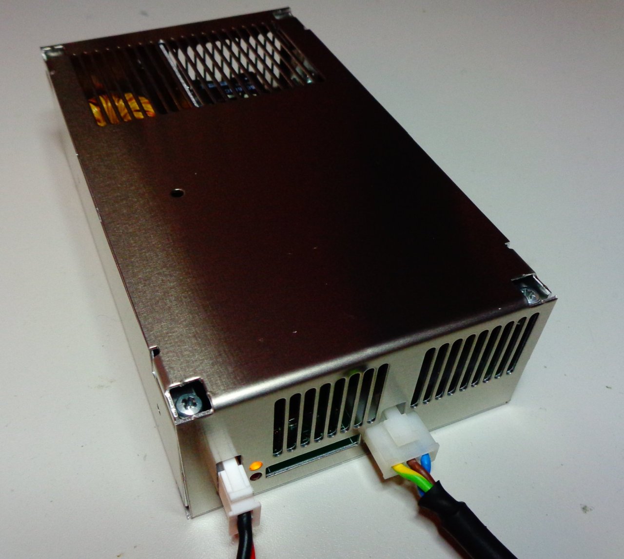
Fig. 1: AC/DC converter prototype r5B4 powered on (fixed output voltage)
The EEZ AC/DC converter (Fig. 1) is designed by taken into account all of the above mentioned issues to become an efficient, affordable and safe power input for the next version of our open source EEZ H24005 bench power supply.
Its main parts are shown in the Fig. 2 That will be described in more details in other sections of this project. Briefly, it’s consists of two sections:
- Variable power output suitable for pre-regulation and
- Four bias outputs with fixed voltage for powering various analog and digital circuits
The variable power output is provided using HV buck and CF-DIC stages controlled by cascaded PWM controller (LM5041B) that drives power transformer with large primary inductance (Lp) that is beneficial for CF-DIC topology following by synchronous rectifier for improved efficiency.
Its output voltage is controlled with tracker circuit that follow change of the post-regulator output voltage. This power output is not intended for the power pre-regulation only – it can be used as an AC/DC converter which output voltage can be accurately trimmed to any output voltage within it wide range from 2.5 to 52.5 V.
The design of this section is based on suggestions from Dragoljub Aleksijević (aka Macola) and was successfully build thanks to his continuous support during development and testing phases.
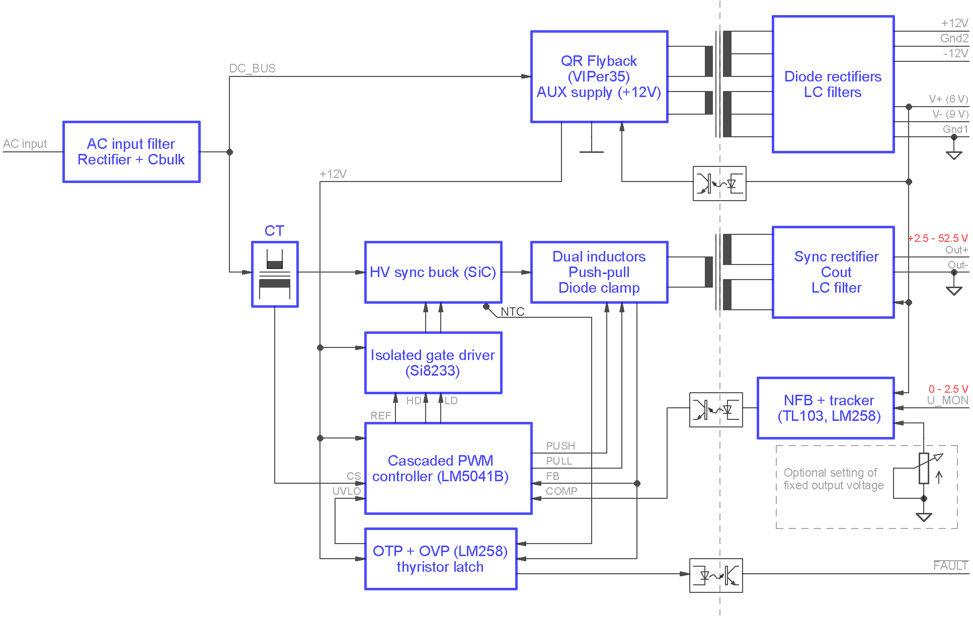
Fig. 2: Power pre-regulator and bias power supply block diagram
Bias outputs is provided using the separate AC/DC converter that use QR (quasi-resonant) flyback topology. The same converter is powering both primary and secondary side of the variable output power stage.
- Open source design
- Wide range input: 85 – 265 Vac, 120 – 380 Vdc
- Wide range output: 2.5 – 52.5 Vdc
- Output current up to 3 A continuously without additional cooling (e.g external fan) or 5 A with additional cooling (max. power up to ~260 W)
- Output voltage controlled by tracker circuit or optionally with multiturn trimpot if fixed output voltage is required
- Cascaded PWM Controller LM5041B (sync buck + push-pull stage)
- Isolated HV power ground and signal ground for improved noise immunity
- HV buck section with high performance SiC MOSFET switches
- High performance VAC Vitroperm 500F core material for power transformer
- Synchronous rectifier with low Rds, on MOSFET switches
- Over-voltage (OVP), short circuit protection and over-temperature protection (OTP) with latched shutdown and opto-isolated open-collector "Fault" output
- Over-current protection (OCP)
- QR flyback as bias power supply (VIPer35)
- Four bias power supply outputs: +6.5 V, -8.5 V and "floating" +12 V / -12 V that can be further regulated with LDOs
- Compact size (155 x 90 x 45 mm)
- Weight (with enclosure): 490 g
This project is an integral part of the EEZ DIB project that is co-financed by the Croatian Agency for SMEs, Innovation and Investments (HAMAG-BICRO) from the Proof of Concept Program (PoC7).