Bias power supply
The bias power supply is a low-power QR flyback that serve two purposes:
- powering of CF-DIC primary and secondary side control circuits and
- provide up to four low power fixed voltage outputs for powering e.g. analog and digital control circuits of the connected post-regulator.
Conventional off-line AC/DC converter that is not designed to provide wide range output voltage variations does not need to have a separate bias power supply. In that case a common practice is to add an auxiliary secondary winding that provides power for primary control circuit. If such converter use synchronous rectification (SR) for improved overall efficiency its SR controller also does not require separate bias supply that use another transformer. Eventually an additional secondary winding is necessary if AC/DC converter output voltage is higher the SR controller allowed supply voltage.
Requirements of AC/DC converter described here is different due to wide range of output voltage. We cannot simply add an additional auxiliary output for powering primary side control circuits. Neither we can do that for powering SR controller. Therefore a separate low-power QR flyback is introduced to provide needed auxiliary voltages. The same QR flyback comes with more outputs to address various power requirements of various post-regulator control circuits.
The core of the bias power supply represents affordable QR flyback controller VIPer35 and custom made transformer provided by Feryster (Poland). VIPer35 comes in convenient SOIC16 package with integrated 800 V avalanche-rugged power MOSFET, has built-in soft-start and many protection mechanisms incl. OCP, OVP, OTP and short-circuit protection.
The bias power supply schematic is shown on Fig. 1. Its AC input section is shared with CF-DIC power section.
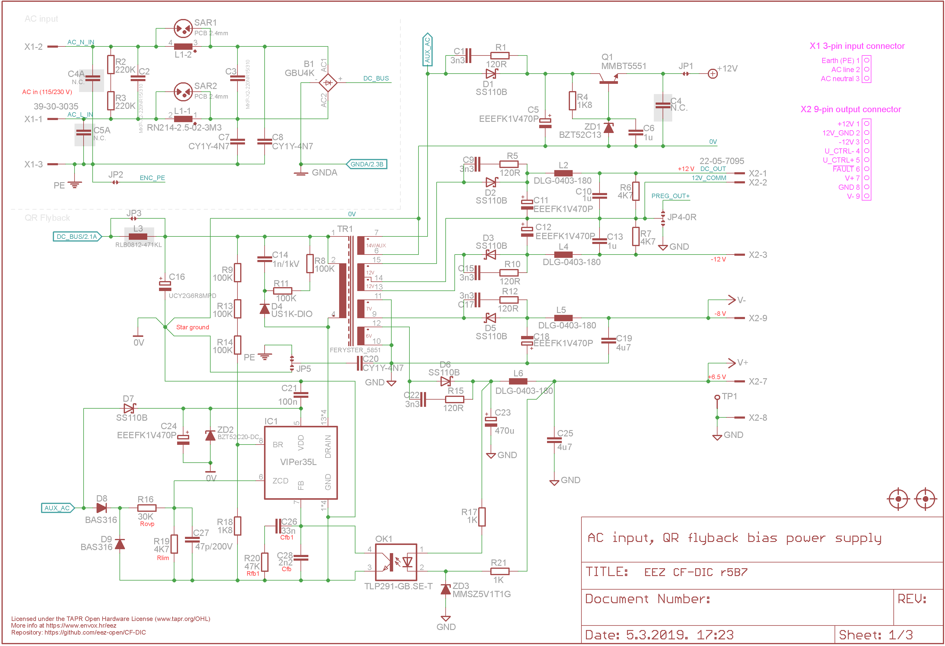
Fig. 1: AC input and bias power supply
Thanks to chosen QR flyback controller the bias power supply accept wide input voltage. Its lower threshold is set with voltage on the BR pin (~80 Vdc) and it goes below lower threshold voltage set on the CF-DIC section. Control loop is closed with opto-coupler (OK1) and the simplest active control element: Zener diode (ZD3). That is done intentionally instead of using usually deployed TL431 type of control since required output voltage tolerance is not tight for powering control circuits on the CF-DIC secondary side. Tightly regulated output voltages are also not needed for the connected post-regulator since it will presumably include LDO’s for final regulation.
The flyback transformer comes with five outputs in total: an auxiliary output for powering VIPer35 and CF-DIC primary side control circuits and four outputs that are grouped in two sections with separate ground connection: 6 V and 7 V secondary outputs are rectified and gives +6.5 V and -8 V. Another two secondary outputs are rectified to give about +12 V and -12 V. One of them is by default connected to the CF-DIC output to “float” above its set voltage that is required for post-regulator with N-channel MOSFET used as “pass” element.
Note that auxiliary output is split into two that VIPer35 primary ZCD (Zero Current Detection) functionality used for quasi-resonant operation is not affected by CF-DIC control circuit load.