Measurements
Thanks to wide input voltage range, the CF-DIC can works with both AC mains voltage. Therefore, measurements for Vin = 230 Vac are presented in the first place. Its behavior with the lower input voltage is shown only if it is significantly different.
Table of contents
- QR Flyback
- CF-DIC power on with and without connected load
- Power on with shorted output
- Power off
- Synchronous Rectification controller
- Output voltage programming
- Output ripple and noise
The following measurements are for no external load connected to any of QR flyback outputs; i.e. it is powering only LED indicator and CF-DIC sections.
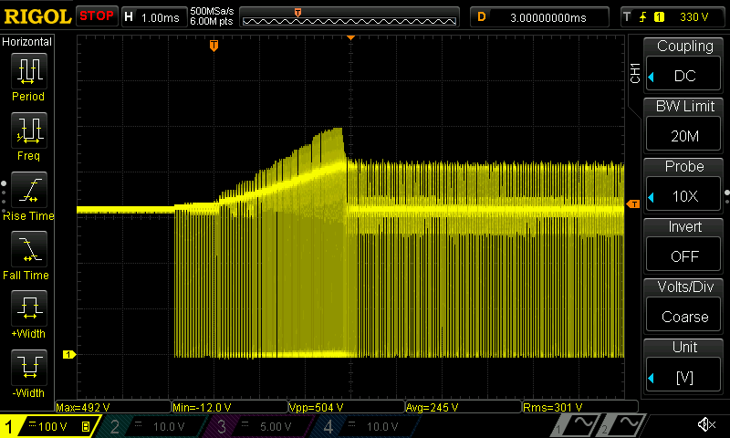
Fig. 1: Power up VIPer35 DRAIN voltage
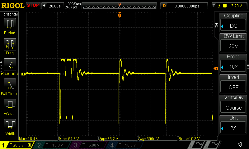
Fig. 2: AUX secondary output (not rectified)
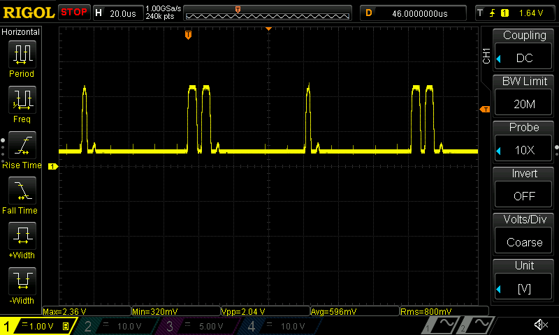
Fig. 3: VIPer35 ZCD input
CF-DIC power on with and without connected load
Observing the CF-DIC’s power output voltage when power is applied is used to check if overshoot exists. A small overshoot is intentionally left since the main purpose of this converter is power pre-regulation and connected load cannot see such voltage disturbance. Having a small overshoot could improve output ripple and noise. Power on without load is shown on Fig. 4. With output voltage set to 25 V. Power on with max. current (5 A) and output voltage set to 48 V is shown in Fig. 5.
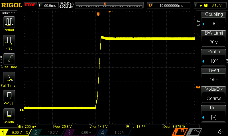
Fig. 4: Power on, Vout = 25 V, no load connected
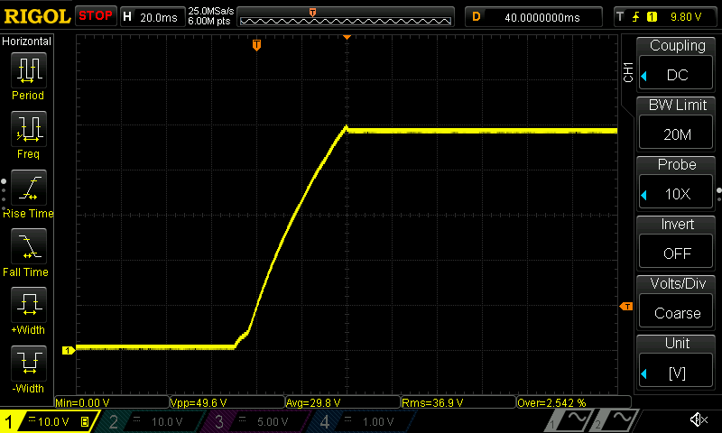
Fig. 5: Power on, Vout = 48 V, resistive load connected, Iout = 5 A
The more demanding scenario is start up when traditional lamp is connected as a load. Its filament, when is cold, has a very low resistance and represents almost a short circuit. The converter has built-in protection against short-circuit (i.e. request to deliver huge current) and it is not tolerated for more then a few hundreds of milliseconds. If connected lamp cannot warm enough during that period, the LM5041B will be shut down and input power recycling is needed for initiate new start of operation.
Such scenario is shown on Fig. 6. for 230 Vac and Fig. 7. for 120 Vac. In both cases the protection acts before connected lamps (four 12 V halogen lamps connected in series) could warm up enough.
Once again, such behavior is intentionally provided, and is not an issue when converter is used as a power pre-regulator.
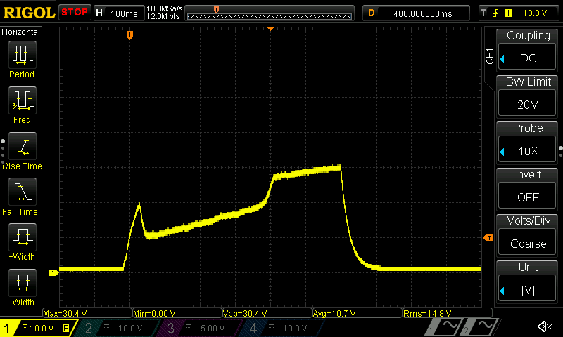
Fig. 6: Power on, Vout = 48 V with halogen lamps connected
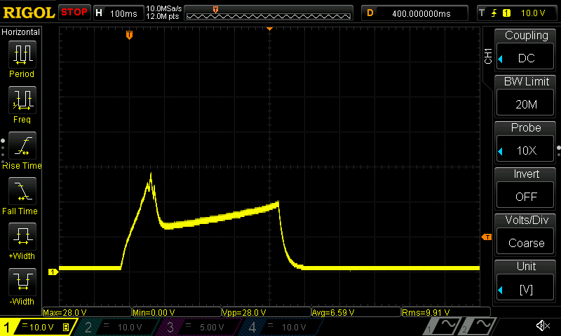
Fig. 7: Power on, Vin=120 Vac, Vout = 48 V with halogen lamps connected
On Fig. 8. is shown HV buck output on start up with shorted output until the protection is tripped. We can see that shut down comes a little bit earlier then with lamps connected since their initial resistance is slightly higher.
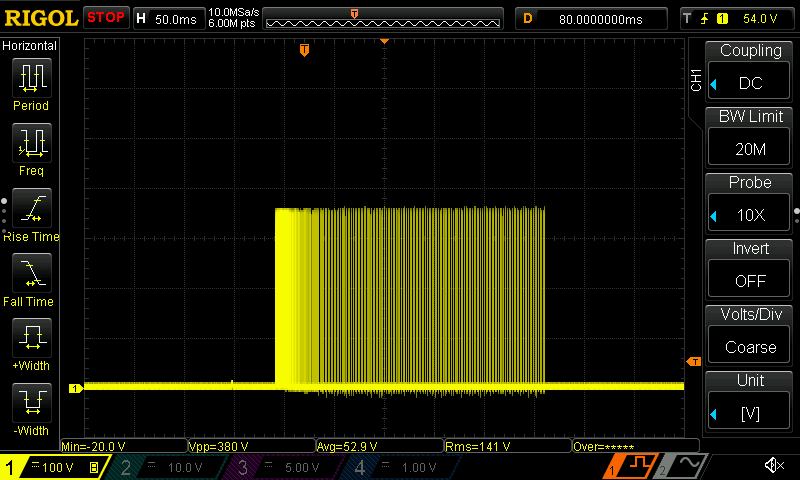
Fig. 8: HV buck output on start up with shorted output
The power off should happen smoothly, without surprisingly high disturbance of the output voltage regardless if the load is connected or not. The Fig. 9. shows output voltage drop with connected bleeder resistor (R70) of 4.7 kΩ and Fig. 10. with resistive 10 Ω load connected.
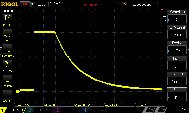
Fig. 9: Power off, Vout = 25 V with bleeder resistor connected (R70)
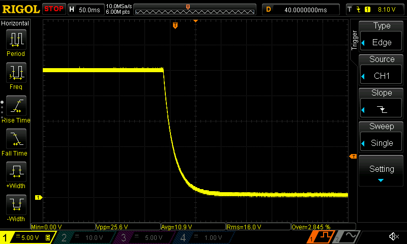
Fig. 10: Power off, Vout = 25 V, Iout = 2.5 A with 10 Ω load connected
Synchronous Rectification Controller
The IR11688 controller incorporates gate voltage regulation function and the gate output shape will vary with connected load. The measurements that follows shown how it looks like for Iout = 1, 2 and 3 A.
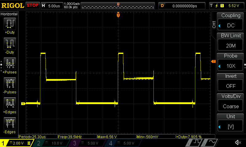
Fig. 11: IR11688 GATE output for Iout = 1 A
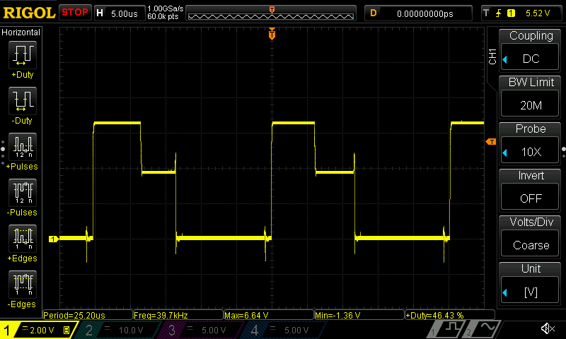
Fig. 12: IR11688 GATE output for Iout = 2 A
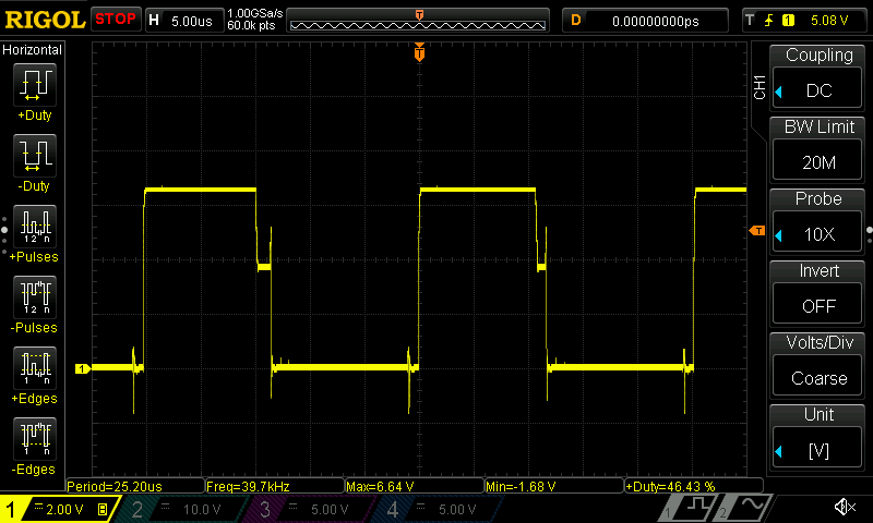
Fig. 13: IR11688 GATE output for Iout = 3 A
An example of voltage across SR MOSFET under load is shown on Fig. 14., and one of IR11688’s controller VR input on Fig. 15.
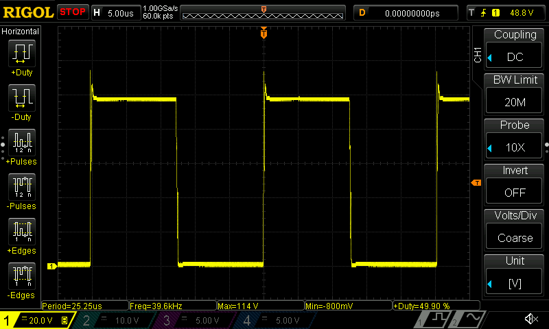
Fig. 14: SR MOSFET Vds for Vout = 48 V, Iout = 5 A
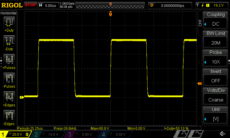
Fig. 15: SR VD input (filtered with 1 kΩ + 47 pF), Vout = 40 V
The CF-DIC’s output voltage, when is working as power pre-regulator, is externally programmed with control voltage applied on its U_Ctrl input (pin 4 and 5 on X2 connector). The following two measurements shows how it is responding on 8 Hz square waveform that produce 4 V (Fig. 16.) and 16 V (Fig. 17.) step on the output. In both case 10 Ω load was connected, causing 0.4 A and 1.6 A change in delivered current. The second case is especially demanding with Vin = 230 Vac: because the feedback loop speed is limited, with such sharp change in output voltage and considerable load, it could easily drive CF-DIC into very dangerous zone (HV buck duty will rise considerably in short time) and damage some of the parts. But, thanks to the implemented Active Duty limiter, it can accept safely such programming sequence for prolonged period of time.
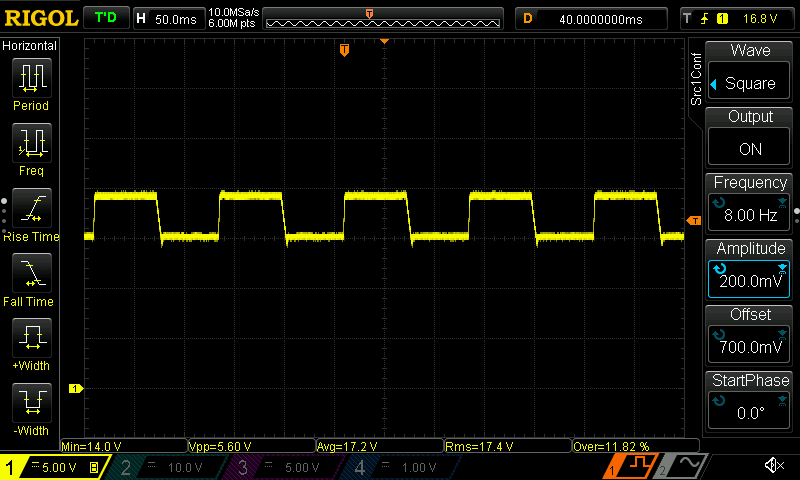
Fig. 16: Output programming (4 V step) with 10 Ω connected load
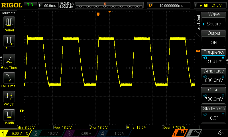
Fig. 17: Output programming (16 V step) with 10 Ω connected load
It is mentioned in the Introduction section that CF-DIC project is initiated by need to replace “off-the-shelf” AC/DC off-line converter. Therefore it is interesting to find out how its output ripple and noise looks in comparison with e.g. Mean Well LRS-150-48 that was used in the EEZ H24005 power supply. The used methodology for testing ripple and noise is rather simple and limited, but if both converters are tested under equal conditions, measured results can be used at least for relative comparison, i.e. to judge which one is “louder” then the other.
The ordinary Rigol x10 probe with spring ground tip is used to measure voltage output across 15 uF (elco) + 100 nF (MFCC) capacitors connected in parallel as shown on Fig. 18. Input bandwidth is limited to 20 MHz.
Output voltage is set to 48 V and output current to 3 A (Mean Well) and 5 A (CF-DIC). The measured level of output ripple and noise in case of CF-DIC is significantly lower for both Vin = 230 Vac (Fig. 19.) and 120 Vac (Fig. 20.).
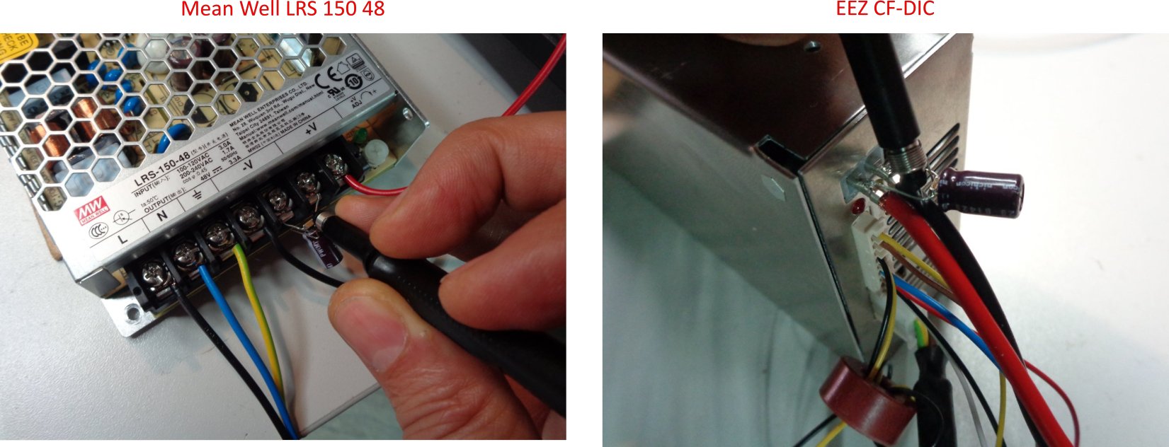
Fig. 18: Output ripple and noise test points
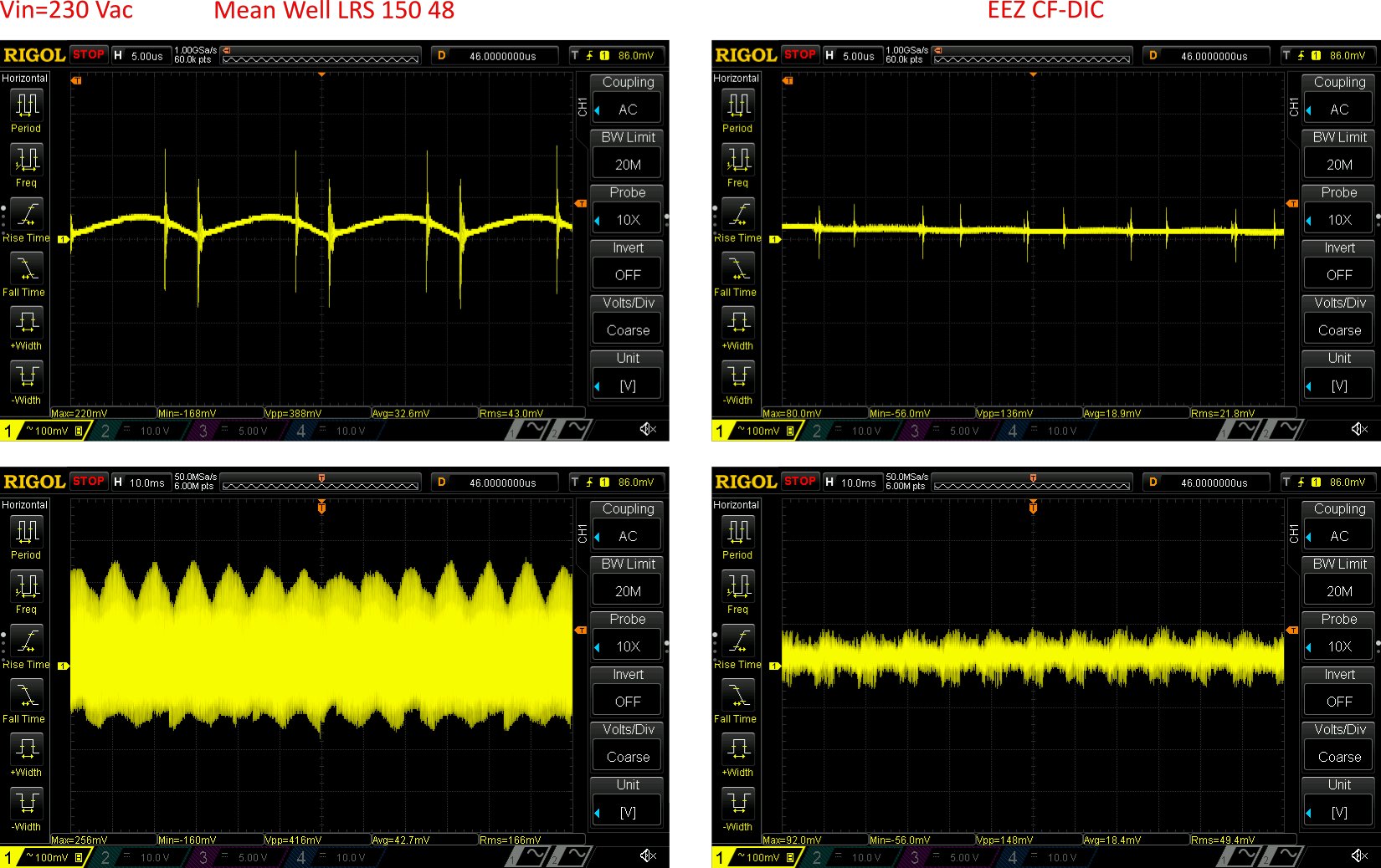
Fig. 19: Output ripple and noise for Vin = 230 Vac
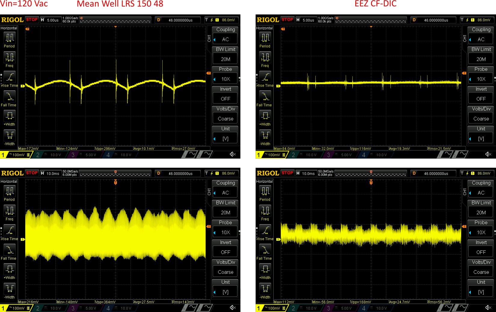
Fig. 20: Output ripple and noise for Vin = 120 Vac