
|
Current version |
v2 |
|
Status |
Active |
|
File repository |
|
|
License |
|
|
Contributions |
|
|
Revision history |
2026-10-10: initial version |
DIB2: An Open-Source Standard for Modular Test & Measurement
The DIB2 (DIY Instrument Bus v2.0) specification defines a modular, plug-and-play architecture for open-source test & measurement instruments. Unlike proprietary standards (PXI, PXIe, VXI) or legacy interfaces (GPIB), DIB2 is fully open-source, hardware-certified for CE/EMC compliance, and designed for accessibility; making professional-grade instrumentation feasible for educational labs, maker spaces, and specialized testing applications. Critically, DIB2 modules are managed and orchestrated through EEZ Studio, a free, open-source GUI development and T&M automation platform that rivals commercial solutions like LabVIEW, VEE, and MATLAB.
The DIB2 version is used in the EEZ BB3+ T&M chassis and is the successor to the existing one used in the EEZ BB3. Backward compatibility is not preserved because of the more advanced architecture used and a larger number of communication interfaces.
Key Design Principles
DIB2 combines:
- Modular flexibility: Mix-and-match modules (half-width, full-width, and 2/3-width) in a 5-slot backplane
- Modern high-speed interfaces: USB 3.x SuperSpeed and PCIe x1 for streaming data; UART/I2C/SPI for control
- Synchronized multi-instrument measurements: 10 MHz distributed clock + trigger bus for coordinated operations
- Inherent safety: Firmware-controlled relay-based power coupling eliminates external wiring hazards
- Unified software stack: EEZ Studio provides drag-and-drop GUI design, visual flow programming (EEZ Flow), and remote T&M automation—eliminating vendor lock-in
- Accessibility: Low cost connectors, open KiCad designs, OSHWA-certified hardware modules, CE-marked reference implementations
DIB2 details
The specification includes two physical connectors, dimensions and front masks of the DIB2 module.
Signal connector
The signal connector is used to communicate with the main processor in the CM5 socket as well as with the SYSMCU located on the BB3+ mainboard. On the DIB2 module, it is a PCB edge connector that plugs into a PCIe x4 64-pin connector. Examples of mainboard/backplane connector models (gold plating of 0.25 µm or thicker, not „flash”) are 10018783-10101TLF and 10018783-11101TLF.
Note: Standard PCIe x4 cards must not be inserted into the DBI2 bus even though they have a compatible connector, because the signal and power pinouts are different. PCIe x1 is provided on DIB2 but with a different pinout as shown below.
The pin mapping is shown in Fig. 1.
The connector features two rows; therefore, the pinout description is divided into two columns (A and B). The direction (Dir column), where applicable, indicates the unidirectional signal flow relative to the inserted module, rather than the mainboard.
DIB2 offers 4 different power rails:
- +12V (4 pins)
- +5V (2 pins)
- +3.3V (2 pins)
- +Vaux (Battery/Supercap backup, max. 3.3 V)
Common GND (mainboard/backplane) is available on 11 pins. PE (Protective Earth) is available on one pin (A1) and has no direct contact with GND.
The BB3+ mainboard uses +12 V as the main power source from which all other voltages are derived, including the +5 V and +3.3 V present on DIB2. The standard total power is 45 W, it can be upgraded to 60 W.
The following interfaces are available for communication with the module:
|
Interface |
Note |
|
I2C/SMbus |
shared among all modules, under the control of the CM5 processor. |
|
UART |
3.3V logic level serial asynchronous communication, shared between all modules and also connected to DIN1 and DOUT1 of the isolated I/O ports on the rear panel of the BB3+. IMPORTANT: For proper operation, RX and TX must be swapped at the module side: the TX coming from the CM5 must be connected to the module’s RX, and vice versa. |
|
SPI |
Three SPI channels; slots 1 and 3 share the first channel, slots 2 and 5 share the second channel, and slot 4 has a dedicated third channel. Each DIB2 slot has two dedicated SPI Chip Select (CS) inputs; CSAn and CSBn and Interrupt Request (IRQ) output (n = 1 – 5). |
|
USB FS/HS |
Each module has a dedicated USB port, requires the implementation of a USB 2 hub on the mainboard/backplane. |
|
USB SS |
Each module has a dedicated USB port, requires the implementation of a USB 3.x hub on the mainboard/backplane. Typically, the same hub can host both USB 2.0 and USB 3.0 ports. BB3+ uses Microchip USB5807C 7-port USB3 hub featuring FlexConnect that enables flexible port switching and host management. It allows a USB hub to dynamically switch between two USB hosts, making any port capable of acting as a host via the FlexConnect feature. Therefore, the host (upstream) can be the CM5 processor (USB Port #0) or a PC when connected to the bottom USB socket (Port #1) on the rear panel of the BB3+. |
|
PCIe |
PCIe x1 interface with PCIe clock request and PCIe WAKE control signals. Requires the implementation of a PCIe switch or Root Complex on the mainboard/backplane. It has not been implemented in BB3+. |
|
Ethernet (optional) |
4-lane Ethernet; requires the implementation of an Ethernet switch on the mainboard/backplane. It has not been implemented in BB3+. |
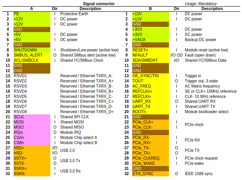
Fig. 1: DIB2 signal connector pin mappings
The following can be used to control the DIB2 module:
|
Name |
Function |
|
SHUTDOWN |
Active low, shared. It is used as a signal to the module to enter low-power mode, but it is not mandatory. It is controlled by the SYSMCU on the BB3+ mainboard. |
|
RESETn |
Active low, dedicated to each module (n = 1 – 5), under the control of the SYSMCU. For example, RESET1 is used to reset the module in slot #1. Upon power-up, all resets are active. It is controlled by the SYSMCU on the BB3+ mainboard. |
|
NFAULT |
An active-low, open-drain signal indicates that one or more modules are in fault mode. The BB3+ SYSMCU processes this signal. |
|
OE_SYNC/TIN |
It is used to synchronize activation of multiple power outputs (Output Enable) or to simultaneously activate other activities (start ADC, DAC on multiple modules, etc.). It is controlled by the CM5 processor. |
|
TOUT |
Trigger output, 3-state, shared among all modules, and optionally the RS485_TX_EN/DOUT2 output on the CM5. Only one module or the CM5 is permitted to generate this signal at any given time; all others must be in the Hi-Z state. |
|
REFCLKn+ |
Single-ended (SE) or positive 10 MHz low-jitter buffered clock source. It is recommended that the processor and peripherals on the module use this as the master clock if better matching of measured data and activity between modules is required. BB3+ offers as an option that the module on slot #5 generates a reference clock of high precision and stability. |
|
REFCLKn- |
Negative buffered clock scource. If used as single-ended, REFCLKn- can be on GND. |
|
BOOTn |
Enables the on-board MCU to enter bootloader mode during reset for firmware uploading/flashing purposes. It is controlled by the SYSMCU on the BB3+ mainboard. Communication in bootloader mode depends on the wiring of the on-board MCU and can be realized via UART, SPI or USB2. Note: each module can be flashed separately. During flashing, it is recommended that all other modules be inactive (use RESETn and/or SHUTDOWN). |
|
ETH_SYNC |
Directly connected to the output (pin 18) of the same name on the CM5 module. Currently not in use. |
Power connector (optional)
BB3+ mainboard has power relays that enable different couplings of the DIB2 module’s power output without the need to use external wiring. This reduces the possibility of errors due to incorrect wiring as well as better control of the output values when the power outputs are connected in series or in parallel.
IMPORTANT: The power module (e.g., DC power source, electronic load, SMU) must have floating outputs/inputs if series, parallel, or split-rail coupling is used.
To enable the aforementioned output coupling, the module must have its power lines connected to the DIB2 power module.
Power connectors are only available for modules in slots #1, #2 and #4.
The pin mapping is shown in Fig. 2.
|
Name |
Function |
|
IN+ |
5 pins for connecting the positive voltage from the DIB2 module to the coupling relays on the mainboard. |
|
OUT+ |
5 pins for connecting the positive voltage that returns from the coupling relays on the mainboard to the output power terminal of the DIB2 module. |
|
IN- |
4 pins for connecting the negative voltage from the DIB2 module to the coupling relays on the mainboard. |
|
OUT- |
4 pins for connecting the negative voltage that returns from the coupling relays on the mainboard to the output power terminal of the DIB2 module. |
|
SENSE+ |
The positive power sense input, which is connected to the rear panel terminal for slots #1 and #2. |
|
SENSE- |
The negative power sense input, which is connected to the rear panel terminal for slots #1 and #2. |
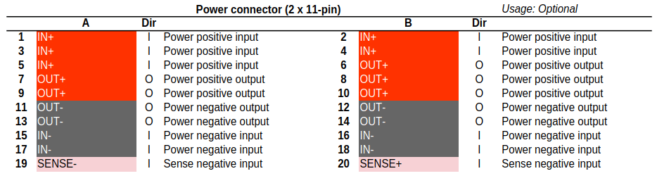
Fig. 2: DIB2 Power connector pin mappings (optional)
The power connector for the DIB2 backplane is a 20-pin, dual-row header with a 0.1" (2.54 mm) pitch, such as PH2-20-UA, 10129381-922002BLF, TSW-110-07-L-D or 77313-124-22LF.
IMPORTANT: No component taller than 5 mm (the height of the power connector) may be placed in the module PCB area where the power connector is located, even if the connector is not being used.
DIB2 module PCB dimensions
The DIB2 specifies only the physical dimensions of the peripheral module and positions of related mandatory and optional connectors (i.e. 64-pin peripheral module PCB edge connector and 20-pin power module). Dimensions of other parts of the system can differ from project to project depending of e.g. chosen enclosure dictated by builder budget and appearance preferences. Allowed dimension of the peripheral module is shown on Fig. 3.
Thanks to the fact that DIB2 connectors are located at the bottom end, the PCB width can vary and it could be anything from 90 to 185 mm. In fact it could be even wider, but this is recommended if the EEZ BB3+ enclosure is used. Recommended PCB height is 95 mm but it can also vary in accordance with selected enclosure, and that is a max. height for the EEZ BB3+ enclosure.
DIB2 introduces a half distance (17.75 mm) in addition to the existing distance between two modules of 35.5 mm (7 HP). Now it is also possible to use up to two 3/2 (53.25 mm) width modules.
The BB3+ mainboard can now accommodate up to 5 modules in different combinations:
|
Module’s count |
Configuration |
|
1 |
Half-width module in any of the 5 slots; full-width in slots #1, #2, #3 (if output coupling is not used) and #4; 3/2-width module in slots #1 or #3. |
|
2 |
The same applies as above, but for two modules. |
|
3 |
Three half-width modules in any of the 5 slots; three full-width modules in slots 1, 2, and 4. The following configurations are also possible: two half-width modules and one full-height module; two half-width modules and one 3/4-width module; or one half-width, one full-width, and one 3/4-width module. |
|
4 |
Four half-width modules, or three half-width modules and one full-width module. Two half-width and two full-width modules (Full-width modules can be installed in all slots except #5 and #3 if output coupling is needed). |
|
5 |
Five half-width modules only. |
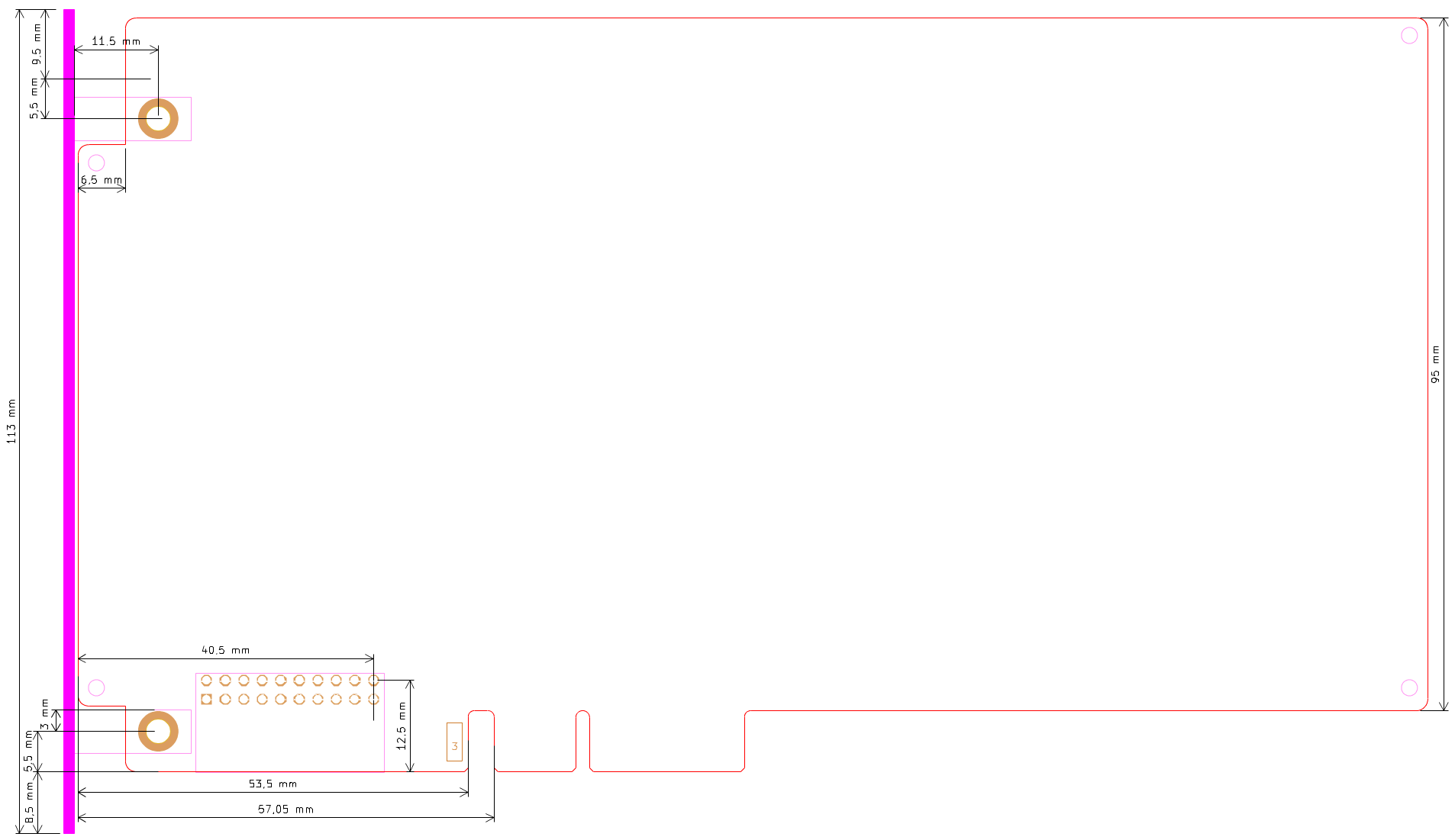
Fig. 3: DIB2 module dimensions
The KiCad template for DIB2 module is available at https://github.com/eez-open/dib-kicad-template
DIB2 front panels
The BB3+ enclosure and mainboard design specifies a front panel thickness of 1.6 mm, which corresponds to the thickness of a standard PCB. This makes it possible to use PCB manufacturers to produce front panels at very affordable prices. The PCB material can be standard FR4, ideally with a blue solder mask and white silkscreen. However, since variations in the shade of blue can occur even with the same manufacturer, it is recommended to use an aluminum PCB version (with black silkscreen), where color inconsistencies should not be an issue.
Fig. 4 and 5 show the dimensions of the half-width and full-width front masks. The half-width front mask has one mounting position, while the full-width has three positions for attachment to the BB3+ enclosure. A countersunk self-tapping screw, such as the B2.2X6.5/B14066 (Bossard), is used for mounting.
Both front masks also feature two mounting holes for attachment to the DIB2 module. M3 PH1 screws (5–8 mm in length) can be used to secure them to the PCB-MB-01 (Essentra) plastic mounting block.
KiCad template for DIB2 front masks is available at https://github.com/eez-open/eez-bb3plus/tree/main/KiCad/Front%20masks and silkscreens at https://github.com/eez-open/eez-bb3plus/tree/main/fabrication/silkscreens (.png must be imported into KiCad PCB Editor using KiCad Image Converter).
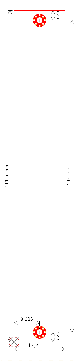
Fig. 4: Half-width DIB2 module front mask
|
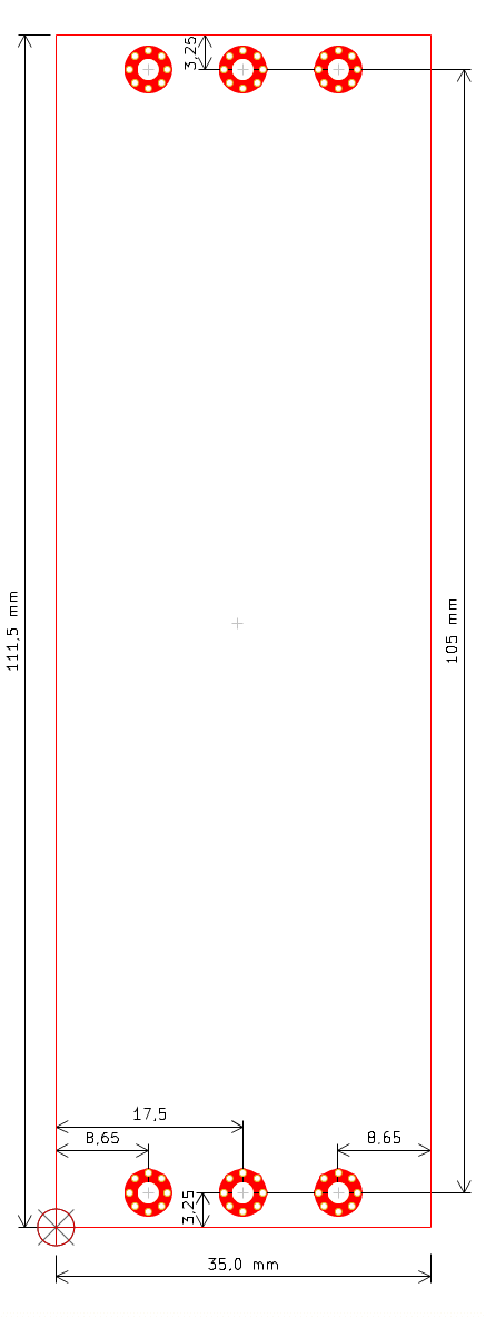
Fig. 5: Full-width DIB2 module front mask
|
DIB2 Strengths
|
Feature |
Implementation |
Competitive Position |
|
Multi-Protocol Communication |
I2C (shared), UART (shared), 3× SPI channels, USB 2.0/3.0 (dedicated per slot), PCIe x1 |
Rivals PXI/PXIe; unique among hobbyist standards |
|
High-Speed Data |
USB 3.x SuperSpeed + PCIe x1 support |
Suitable for digitizers, waveform generators, data acquisition at modern speeds |
|
Clock Distribution |
10 MHz reference clock (single-ended + differential), with optional high-precision oscillator from slot #5 |
Enables synchronized multi-module measurements; professional-grade timing |
|
Trigger Synchronization |
OE_SYNC/TIN (input) + TOUT (output, 3-state, open-drain) |
Cross-module coordination for power ramp, ADC start, etc. |
|
Flexible Power Architecture |
Mainboard relays for series/parallel/split-rail coupling; 45–60 W power budget |
Eliminates external wiring errors; firmware-controlled safety |
|
Modular Design Flexibility |
Half-width (17.75 mm), full-width (35.5 mm), 3/2-width (53.25 mm) modules; up to 5 slots |
Unprecedented density and configuration flexibility for custom systems |
|
Modern Isolation Strategy |
Isolation implemented per-module as needed (avoids one-size-fits-all overhead) |
Cost-effective for low-isolation modules; flexible for high-V designs |
|
Firmware Management |
Dedicated BOOTn per slot; can flash individual modules independently Robust OTA updates; debugging without removing modules |
|
Competitive Advantages vs. Proprietary Standards & Software
|
Metric |
DIB2 + EEZ Studio |
PXI + LabVIEW |
PXIe + VEE |
GPIB (legacy) |
Custom Python |
|
Hardware cost |
$$ |
$$$$$ |
$$$$$$ |
$$ |
$$ |
|
Software cost |
FREE |
$$$$ |
$$$ |
FREE (old) |
FREE (time) |
|
High-speed I/O |
✓ USB 3.x, PCIe x1 |
✗ |
✓✓✓ |
✗ |
✓ |
|
Modularity |
✓ Half / full / 3/2-width |
✓ |
✓ |
✓ (VXI racks) |
~ |
|
Synchronized measurement |
✓ 10 MHz clock + trigger |
✓✓ |
✓✓✓ |
~ |
~ |
|
Open-source (hardware) |
✓✓✓ |
✗ |
✗ |
✗ |
✓ |
|
Open-source (software) |
✓✓✓ |
✗ |
✗ |
✗ |
✓ |
|
No-code/Low-code GUI |
✓ (EEZ Flow) |
✓ |
✓✓ |
✗ |
✗ |
|
Vendor lock-in |
None |
High |
High |
Obsolete |
None |
|
Learning curve (non-programmers) |
Shallow |
Steep |
Moderate |
Shallow (outdated) |
Steep |
|
CE-certified designs |
✓ (reference modules) |
✓ |
✓ |
✗ (pre-2000s) |
✗ |
|
Educational accessibility |
✓✓✓ |
✗ |
✗ |
✗ |
✓ |
Key insight: DIB2 + EEZ Studio is the only combination that provides:
- Hardware modularity and open-source ecosystem
- Professional T&M capabilities and zero licensing costs
- Modern high-speed I/O and legacy instrument support (via VISA/GPIB adapter)
- Drag-and-drop GUI design and industrial-grade automation scripting
Ecosystem Maturity
DIB2 is not theoretical – three production-ready modules, one certified mainboard, a complete software stack, and an active developer community demonstrate real-world applicability:
- ✓ Open KiCad schematics for all reference designs
- ✓ OSHWA hardware certification (HR000123, HR000120, HR000124)
- ✓ CE marking + EMC pre-certification reports
- ✓ Full firmware source code
- ✓ EEZ Studio with 40+ project templates and IEXT catalog
- ✓ Long-term funding via NLnet foundation
- ✓ Active GitHub repositories (50+ contributors)
Third-party developers can:
- Fork reference designs (DCP405+ or MIO168+) as a template
- Adapt DIB2 pinout for their specific instrument
- Create IEXT instrument definitions in EEZ Studio
- Validate against the open specification
- Contribute back to the ecosystem (IEXTs, firmware, EEZ Studio plugins)
EEZ Studio Core Features for DIB2
- EEZ Flow: Visual, low-code/no-code flowchart programming for complex multi-instrument automation
- IEXT (Instrument EXTensions): Pre-built instrument definitions for BB3+, DCP405+, MIO168+; can define custom SCPI commands
- Session-oriented data logging: Capture measurements, create searchable databases, export to CSV
- Offline waveform analysis: FFT, harmonic analysis, period/frequency calculation
- Instrument Terminal: Interactive SCPI command entry with context-sensitive help
- Multi-language support: Deploy custom GUIs in any language (LTR/RTL)
- C++ code generation: Export GUIs for embedded systems (e.g., BB3+ touchscreen native apps)
- No royalties: Output code is royalty-free (MIT, BSD 2.0, or Public Domain)
Typical Applications
DIB2 + EEZ Studio is particularly suited for:
|
Application |
Why DIB2 Excels |
|
Educational labs |
Open-source, affordable, easy to repair and modify; EEZ Studio teaches modern GUI/automation concepts |
|
Renewable energy testing |
Multiple power modules + EEZ Flow for multi-phase system validation; synchronized measurements via 10 MHz clock |
|
Power electronics development |
Accurate isolated measurements + oscilloscope-class waveform capture; FFT/harmonics analysis in EEZ Studio |
|
Automated test & measurement (ATE) |
Synchronized multi-module operation + visual programming = rapid deployment; unattended logging via Linux CM5 |
|
IoT sensor validation |
Mixed I/O module for digital/analog stimulus; EEZ Studio dashboards for real-time trending |
|
RF/microwave front-ends |
USB 3.x streaming for high-sample-rate digitizers; custom GUIs built in hours vs. weeks in LabVIEW |
|
Production line testing |
Low-cost multi-channel measurements; EEZ Flow automation for pass/fail sequences; no per-seat licensing |
|
Legacy instrument control |
VISA/GPIB adapters allow DIB2 to coexist with older equipment; EEZ Studio unified interface for all devices |