|
Current version |
r1B3 |
|
Status |
Completed, ready for production |
|
PCB manufactured |
r1B3 |
|
PCB assembled |
r1B3 |
|
BOM |
Yes (TME, Mouser, Digikey, Farnell, RS) |
|
File repository |
https://github.com/eez-open/dib-mux14d (include Eagle, Gerber and BOM files) |
|
License |
|
|
Contributions |
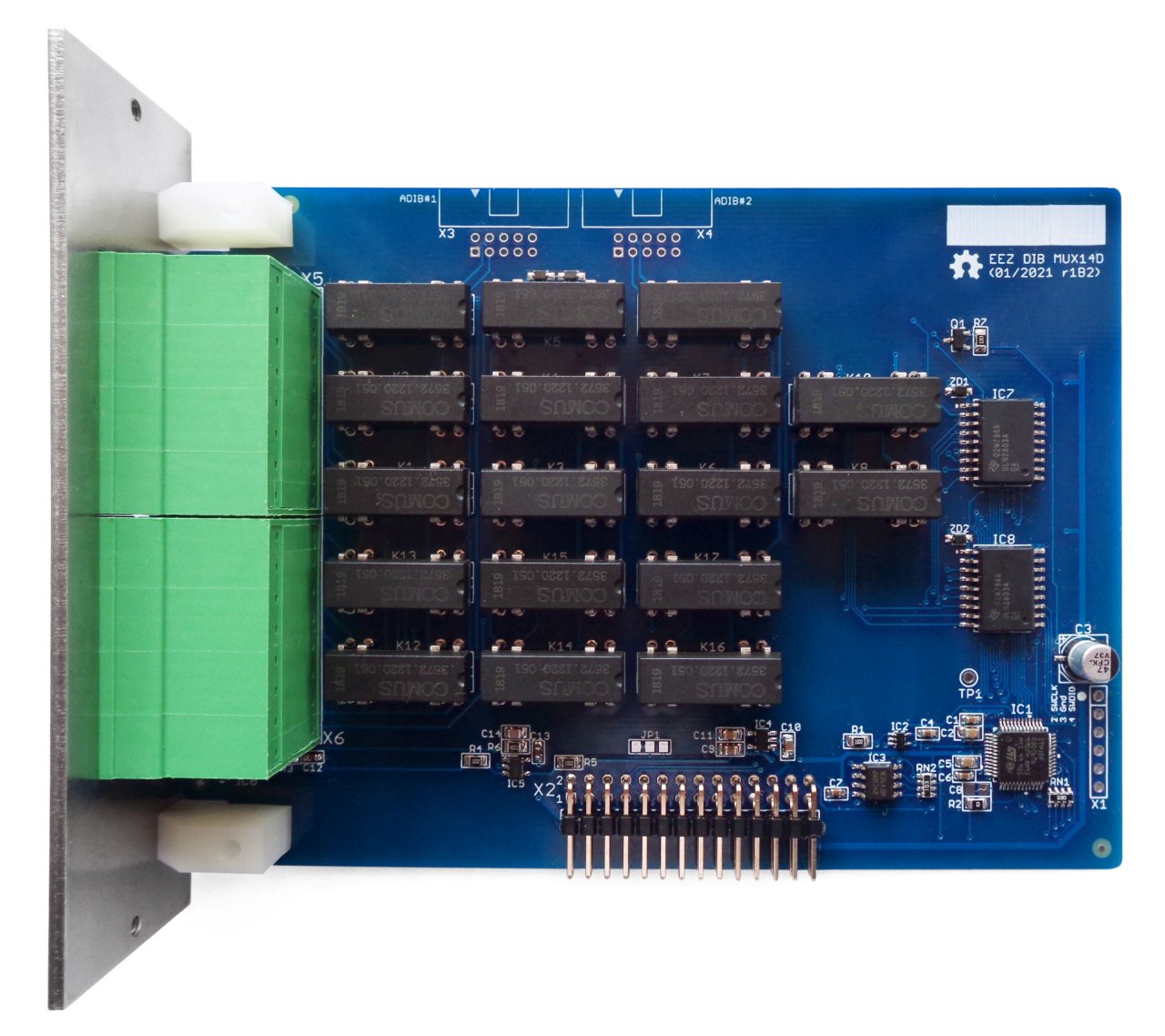
Fig. 1: MUX14D PCB prototype r1B2
Feature list
- On-board STM32F030C6T6 ARM Cortex-M0 Value line MCU, 32 KiB Flash, 48 MHz CPU, LQFP-48 package
- 2 x 16-pin dual row 3.81 mm connectors
- 2 x ADIB connectors (10-pin 2 mm)
- Dual 2-wire 1:7 reed relay multiplexer switchable to 1:14 multiplexer
- Reed relay max. switching power: 10 W, max. switching voltage: 150 VDC
- Reed relay max. switching current: 0.5 A, max. carry current: 1 A
- “Cold junction” temperature sensor
- On-board +3.3 V LDO
- Firmware download via UART
- Optional SWD for debugging
- I2C EEPROM for storing board specific parameters
- Dimensions: 131 x 95 mm, 2-layer PCB
The MUX14D module features dual 2-wire 7:1 reed relay multiplexer that can be combined in single 14:1 multiplexer. Multiplexer output is exposed on front panel terminal or can be connected (firmware controlled) to ADIB that offer internal wiring with other modules (e.g. MIO168).
The module has two 16-pin 3.81 mm connectors on the front panel thanks to which it is possible to quickly and easily connect the wires without the need for an additional breakout box. 8-way pluggable female terminal connector blocks in low-profile push-in and screw-fasten variants can be used to connect the wires.
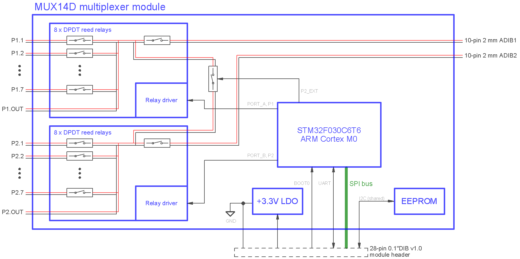
Fig. 2: MUX14D block diagram
EEZ DIB interface
The SMX46 module interface with the MCU module is accomplished over the 28-pin 0.1” right angled header (X2).
On-board I2C EEPROM (IC3) provides storage for module-specific information such as its ID, analog outputs calibration data, working hours counters and relay switch cycles. Its address is defined by RN2-2 to RN2-4 pull-up resistors and ground connections on the backplane.
The STM32F030C6T6, a mainstream ARM Cortex-M0 Value line MCU with 32 KiB Flash, 48 MHz (IC1) is used to control power relays and to communicate with the master MCU on the MCU module.
UART and BOOT0 are used to program its flash memory, a process that is controlled by the master MCU and can be easily done via a touchscreen screen without the need for an external programmer/ debugger (ST-Link or similar). 3-state buffer (IC2) is used to control the UART TX output which can only be active while downloading the firmware to flash memory.
The powering of the MCU and all logic is done via 3.3 V LDO (IC4) which uses +5 V from DIB.
Two 10-pin 2.0 mm ADIB connectors (X3, X4) are used for internal connectivity with other modules (e.g. MIO168): P1 multiplexer output could be connected to ADIB #1 and P2 output to ADIB #2. MUX14D ADIB ID is set to 002.
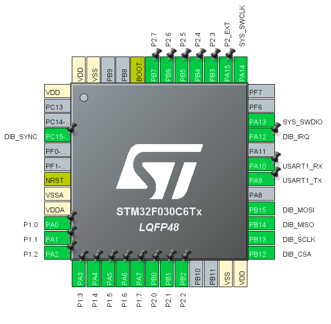
Fig. 3: MCU pin assignment (CubeMX) for r1B2 version
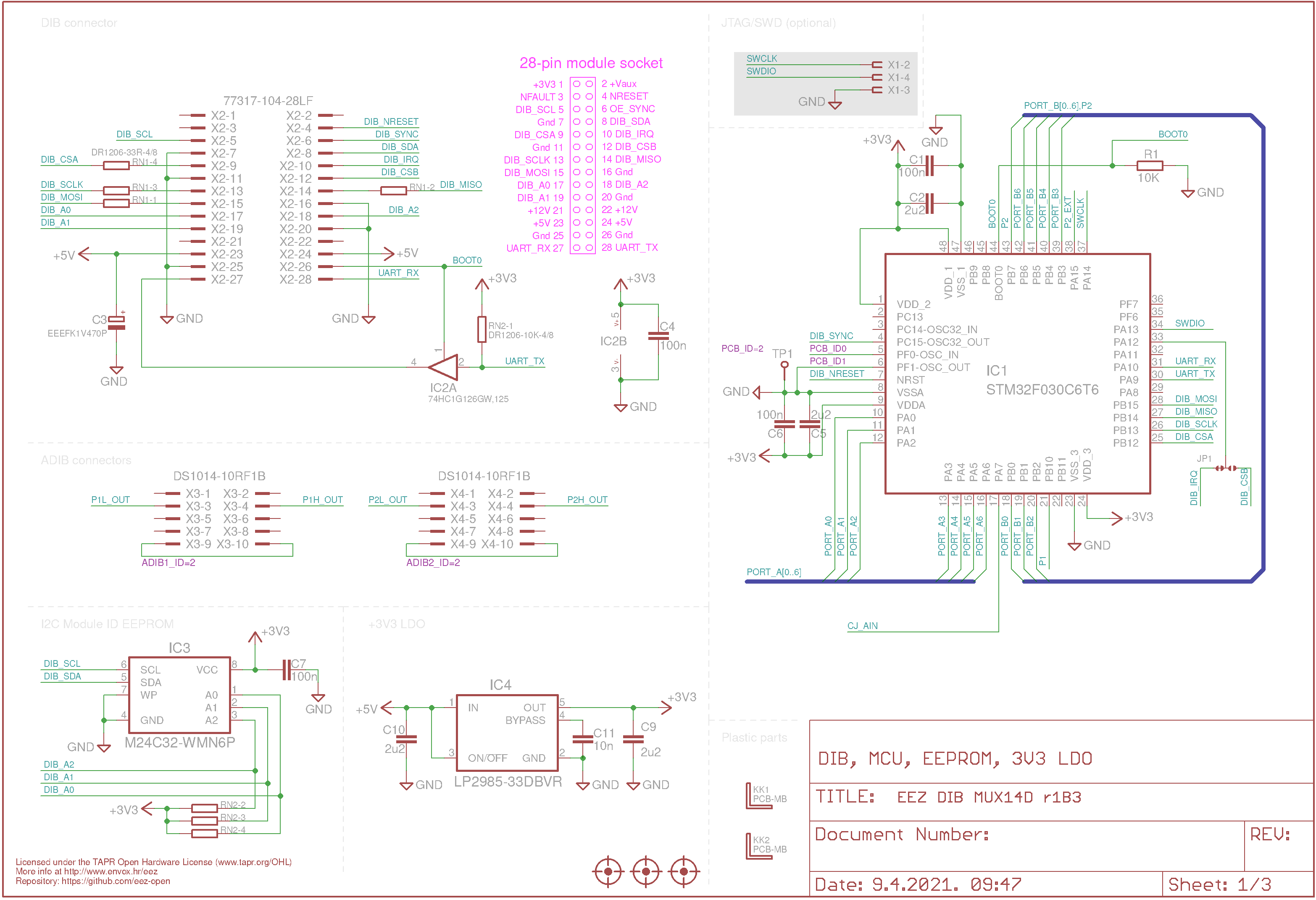
Fig. 4: DIB, ADIB, power, EEPROM and MCU
Reed relay multiplexers
Dual 2-wire 7:1 multiplexers are accomplished with two group of low power reed relays (K1-K7 and K10-K16). Multiplexer outputs are exposed to front panel terminals (pin X6-15, X6-16 and X6-7, X6-8). Outputs could be selectively applied to ADIB connectors that provides internal wiring to other DIB modules equipped with ADIB connections.
Multiplexer outputs can be combined to make a single 14:1 multiplexer by using to K8 relay.
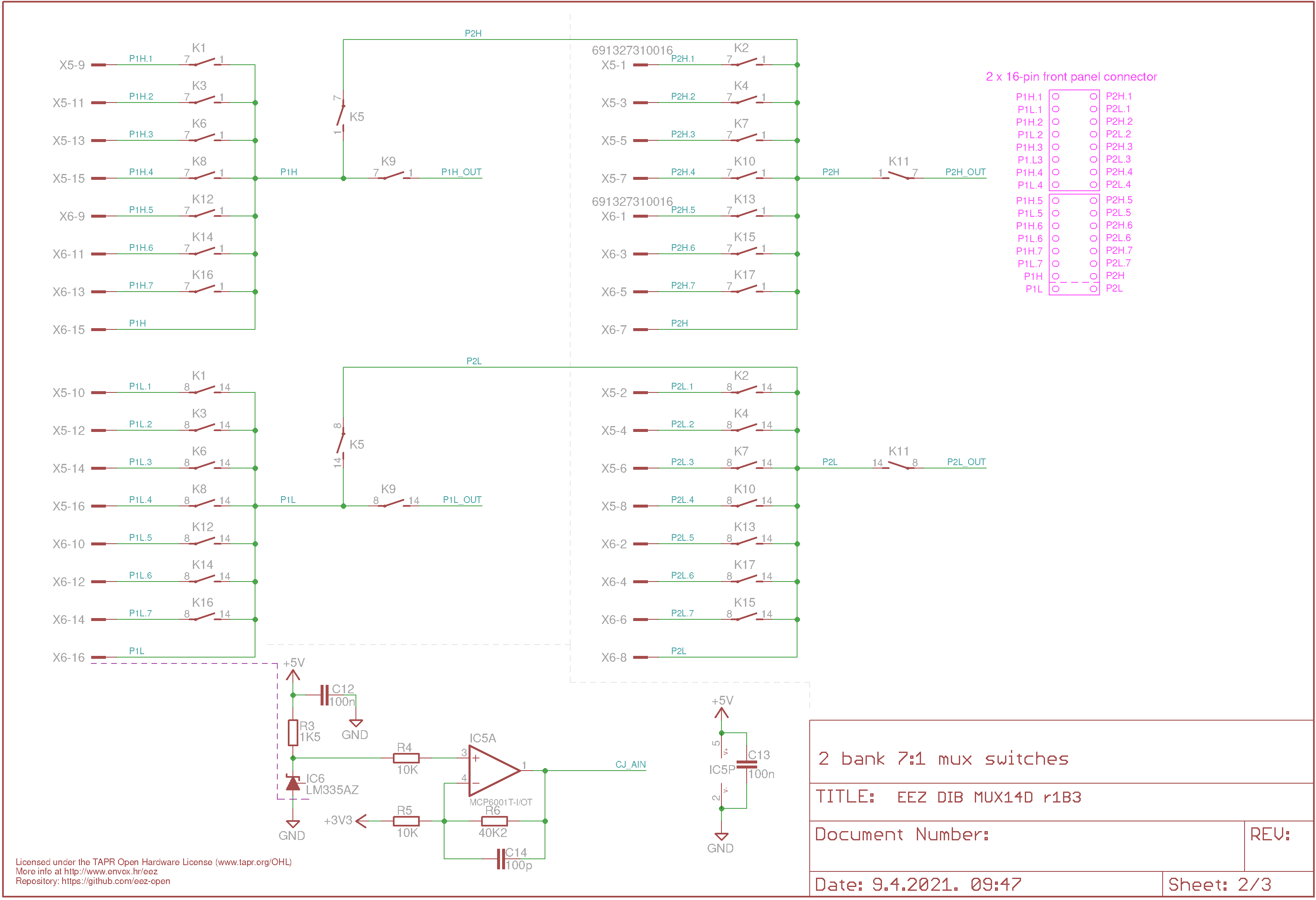
Fig. 5: Multiplexer switches
Two 8-port darlington drivers (IC7, IC8) are used to drive two group of reed relays (K1,K3, K6, K8, K12, K14, K16, K9 and K2, K4, K7, K10, K13, K15, K17, K11). Selected drivers feature protection diodes whose common outputs are connected using zener diodes (ZD1, ZD2) at +5 V.
The remaining relay (K5) has a separate driver (Q1) with protection diodes (D1, ZD3).
“Cold junction” temperature sensor
The module also has a "cold junction" sensor for temperature compensation in case thermocouple sensors are connected to the inputs. The output voltage of the LM335A (1% error) sensor used gives 10 mV/K or about 2.93 V for room temperature (20 degrees Celsius). This voltage was applied to an attenuating operational amplifier (IC5) to extend the temperature range from 0 to 55 degrees Celsius to approximately the full scale of the ADC in the MCU (i.e. 400 mV to 3.2 V) for better measurement accuracy.
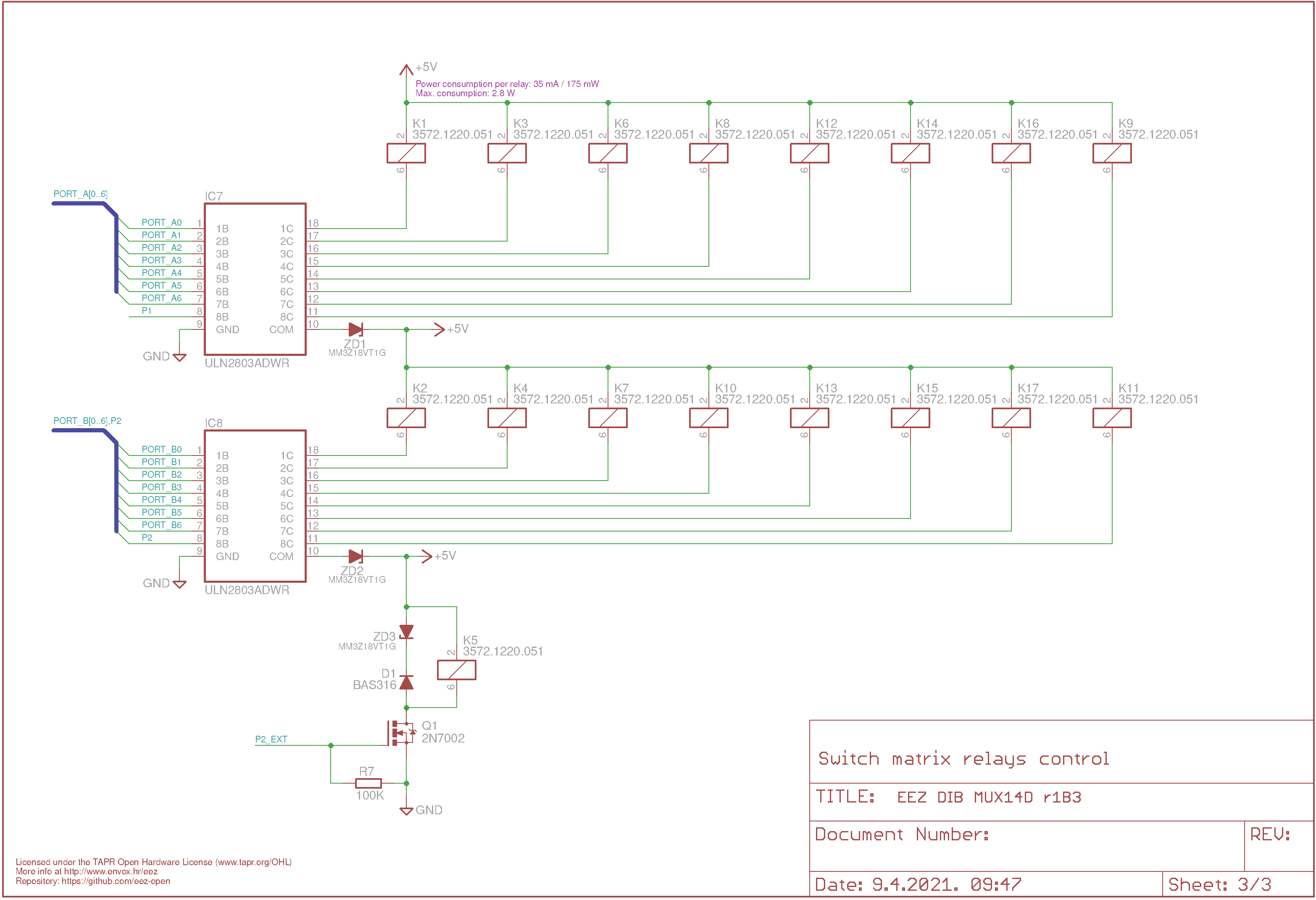
Fig. 6: Multiplexer drivers