|
Current version |
r1B3 |
|
Status |
Completed, ready for production |
|
PCB manufactured |
Yes (r1B2) |
|
PCB assembled |
Yes (r1B2) |
|
BOM |
Yes (TME, Mouser, Digikey, Farnell, RS) |
|
File repository |
https://github.com/eez-open/dib-prel6 (include Eagle, Gerber and BOM files) |
|
License |
|
|
Contributions |
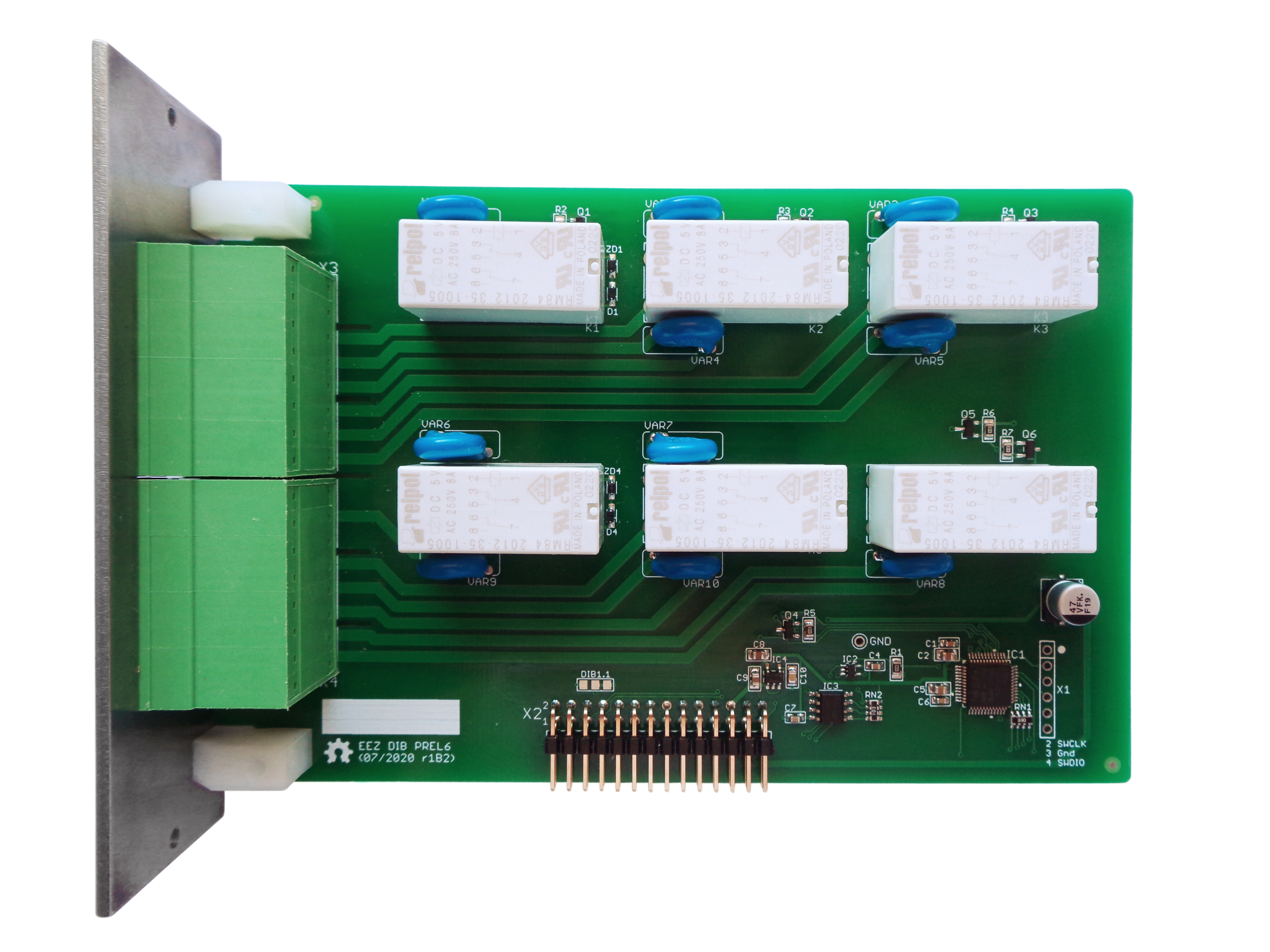
Fig. 1: PREL6 r1B2
Feature list

- On-board STM32F030C6T6 ARM Cortex-M0 Value line MCU, 32 KiB Flash, 48 MHz, LQFP-48 package
- 2 x 16-pin dual row 3.81 mm connectors
- 4 x SPDT relays, max. 8 A / 230 Vac
- 2 x SPST relays, max. 8 A / 230 Vac
- On-board +3.3 V LDO
- Firmware download via UART
- Optional SWD for debugging
- I2C EEPROM for storing board specific parameters
- Dimensions: 146 x 95 mm, 2-layer PCB
PREL6 is a simple module designed to control up to six power circuits using standard DPDT (Double-Pole Double-Throw) relays for currents up to 8 A per contact. The module has two 16-pin 3.81 mm connectors on the front panel thanks to which it is possible to quickly and easily connect the wires without the need for an additional breakout box. 8-way pluggable female terminal connector blocks in low-profile push-in and screw-fasten variants can be used to connect the wires (Fig. 2).
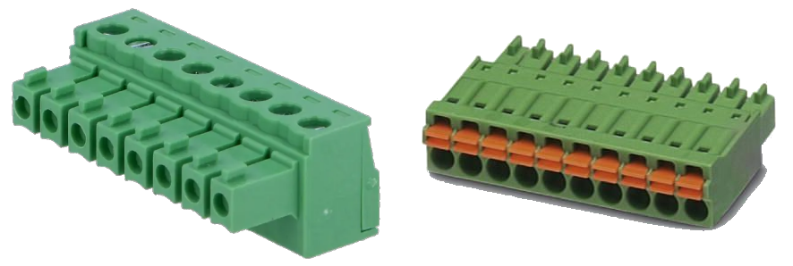
Fig. 2: Pluggable terminal block variants
Although they are DPDT relays (form C), the two channels (K1 and K6) have only two contacts exposed which makes them SPST (form A) due to the limited number of pins on front panel connectors (X3, X4) because two pins per contract were used for the central four channels (K2 to K5) .
The distance between the lines on the PCB is no less than 0.89 mm (35 mils), which for coated conductors can enable work with AC mains of 230 Vac (according to IPC2221 recommendations).
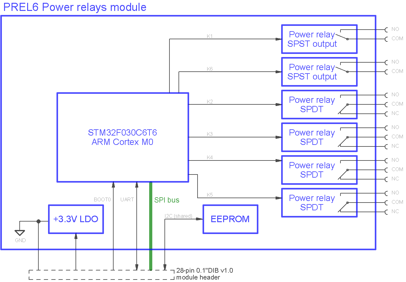
Fig. 3: PREL6 block diagram
EEZ DIB interface
The PREL6 module interface with the MCU module is accomplished over the 28-pin 0.1” right angled header (X2).
On-board I2C EEPROM (IC3) provides storage for module-specific information such as its ID, working hours counters and relay switch cycles. Its address is defined by RN2-2 to RN2-4 pull-up resistors and ground connections on the backplane.
The STM32F030C6T6, a mainstream ARM Cortex-M0 Value line MCU with 32 KiB Flash, 48 MHz (IC1) is used to control power relays and to communicate with the master MCU on the MCU module.
UART and BOOT0 are used to program its flash memory, a process that is controlled by the master MCU and can be easily done via a touchscreen screen without the need for an external programmer/ debugger (ST-Link or similar).
The powering of the MCU and all logic is done via 3.3 V LDO (IC4) which uses +5 V from DIB.
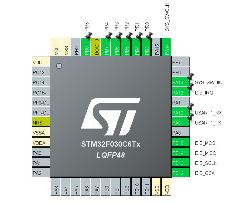
Fig. 4: MCU pin assignment (CubeMX) for r1B2 version
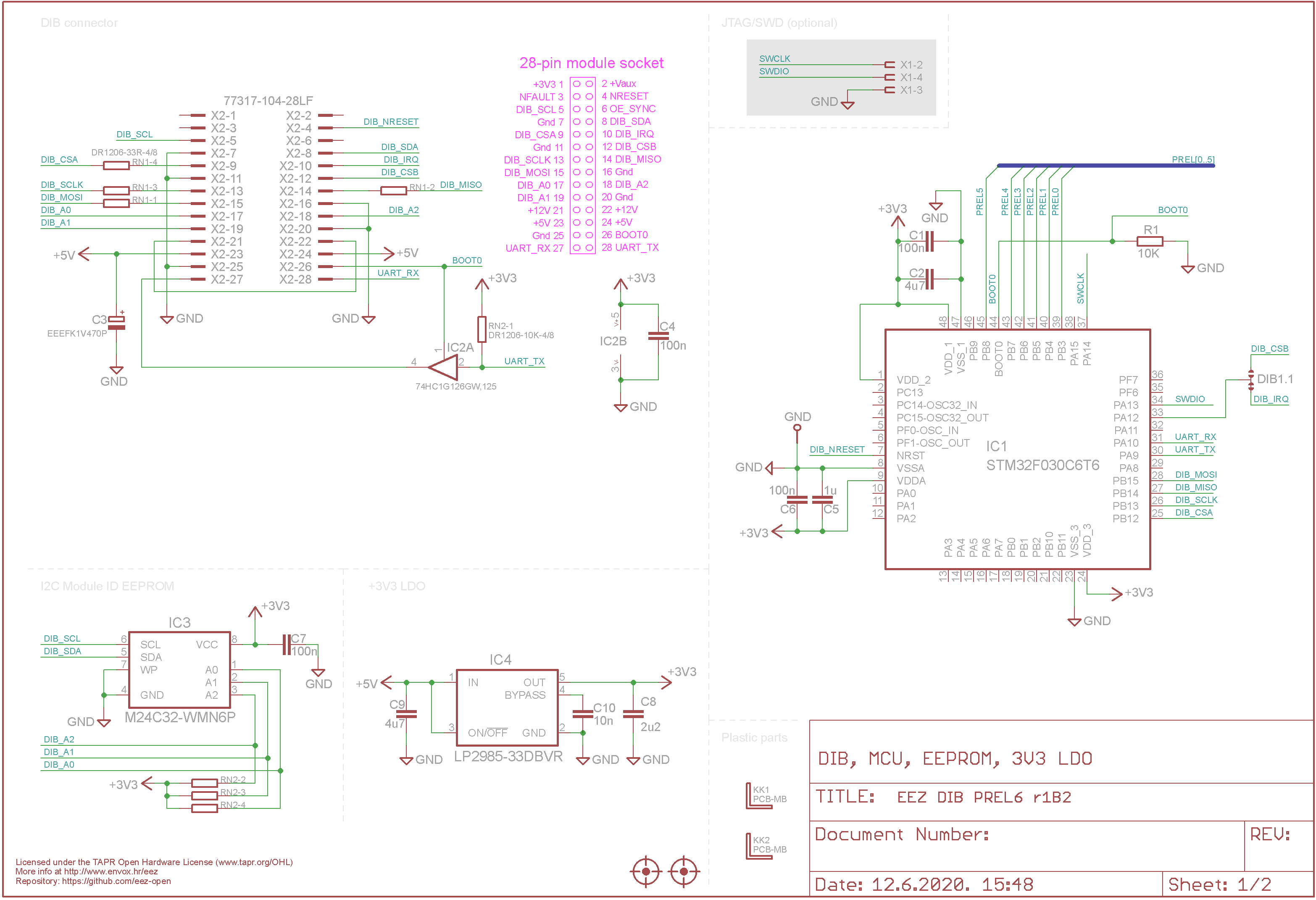
Fig. : DIB, power, EEPROM and MCU
Power relays
Low power MOSFETs (Q1 to Q6) are used to drive the relays, whose inputs also have pull-down resistors (R2-R7) for better immunity.
Relay coil suppression is accomplished by a combination of rectifier (D1 to D6) and zener (ZD1 to ZD6) diodes. This affords the best compromise both to coil switch protection (MOSFET) and relay switching performance and reliability.
Finally, the contacts are additionally protected by varistors (VAR1 to VAR8, one per contact position), which will help in case of inductive load switching.
Relays when active consume 80 mA, so the max. consumption is 480 mA or 2.4 W on +5 V power rail. For this reason, it is not recommended to use more than two such modules in a single BB3 enclosure.
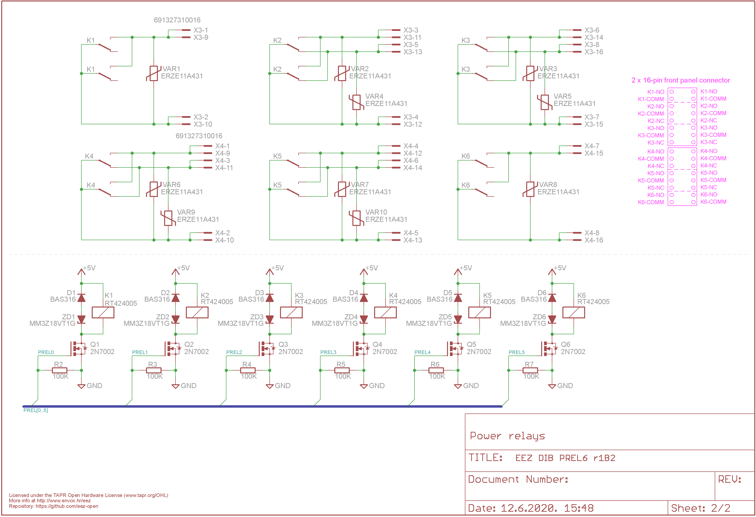
Fig. : Power relays