Welcome to Web Simulator
In the process of developing the firmware for BB3, we created a simulator that simplified and accelerated the development of certain functions without the use of physical BB3 device (because they were not available or were occupied by other tasks). Here you can try out the web version of the simulator quickly and easily without having to install anything locally on your computer.
The web simulator offers a unique opportunity to evaluate almost all the functionality of BB3 with various modules to help you in the purchase decision process. It has been successfully tested on various browsers. Note that it is not possible to run it on Firefox in Private mode and TOR browser (You will get an error message: Exception thrown, see JavaScript console). The brief instructions below describe what will need to be done to successfully evaluate BB3 functionality.
The web simulator does not allow the evaluation of all the functionality of the physical device, so for example you will not be able to test the Ethernet connection or run MicroPython scripts. Also on a physical device, some functions are performed faster and more accurately (e.g. output programing lists).
First Start
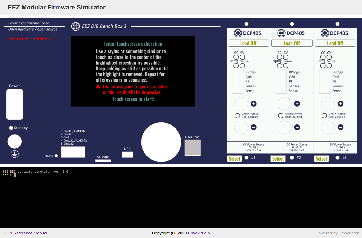
At the first start, you will receive a welcome message for calibrating the touchscreen as shown below. Follow the instructions and use the mouse to select the calibration points. Once the touchscreen calibration has been saved, you will no longer be asked for a new calibration on that browser the next time you start it.
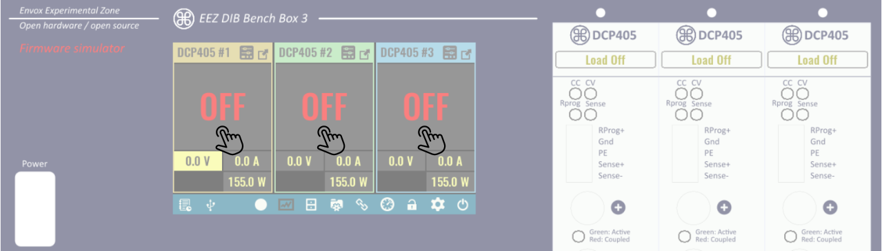
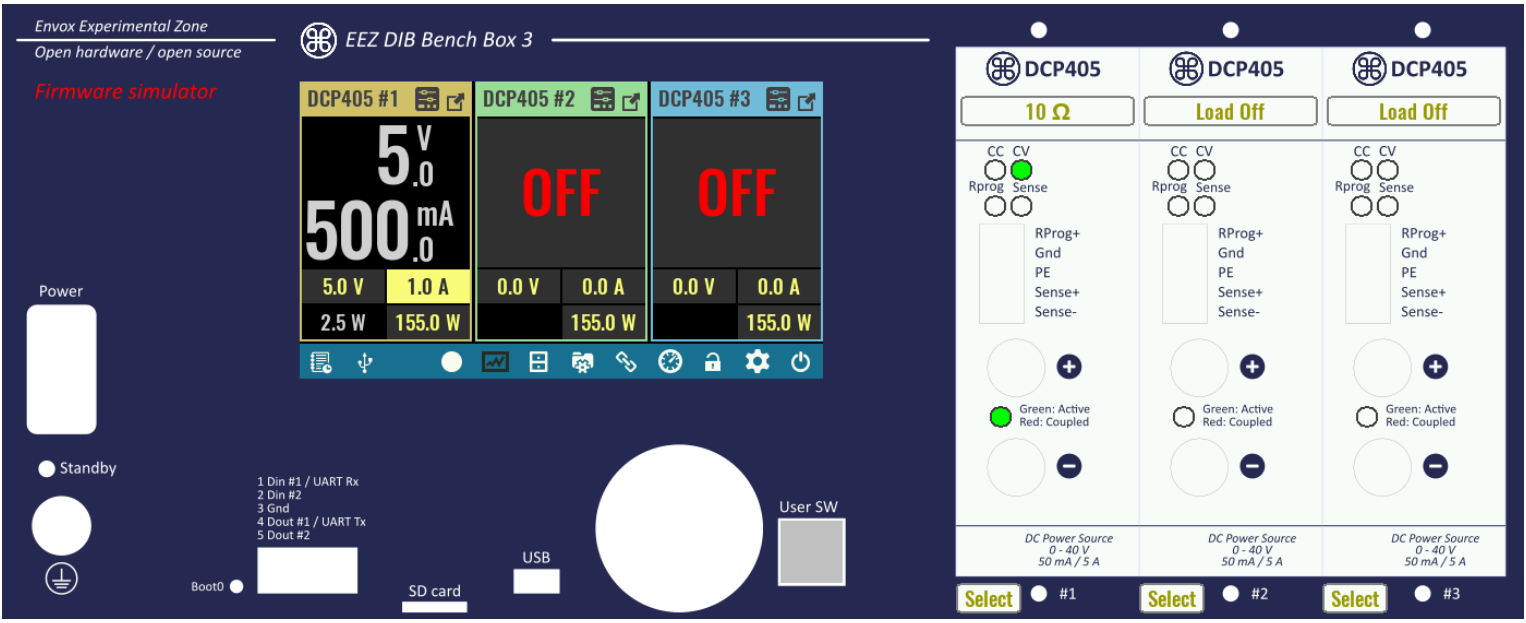
After the calibration is completed successfully, a home page will appear showing you three default modules (DCP405) with a message to set the datetime. You can select "No" and the simulator will take the system datetime. At the start the outputs of all selected modules will be switched off. The outputs can be set to ON by clicking in the area where OFF is displayed.
The first time you turn on the power module output, a message will appear: Do you want to calibrate channel?. For now, you can skip this or leave it for later by selecting the "No" or "Later" option (calibration is described in Chapter 12 of the User manual). You can now set the output values of each power channel as desired, as well as navigate through all GUI menu options.
User sw button is also functional and you can use the mouse wheel instead of the encoder knob.
To test the output current and power, it is even possible to attach a load to the output of the power channel. At the start, all loads are turned off, and you can turn them on and set their ohmic value (default is 10 Ω) as in the picture:
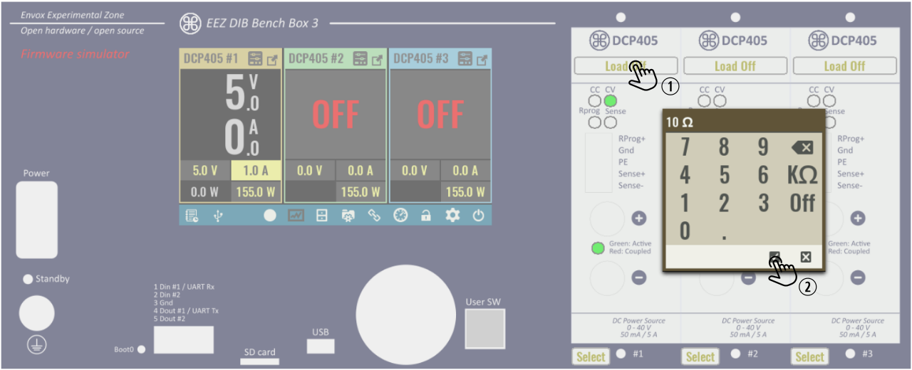
After successfully applied the load with set 5 V and current of 1 A, the output of the first channel will be in CV mode (green LED), the measured current will be 0.5 A and power 2.5 W.
If you reduce the load to e.g. 2 Ω, the output voltage will drop to 2 V due to the set current limit of 1 A and the output mode will change to CC (red LED).
Module selection
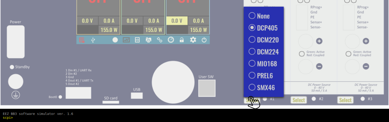
In the web simulator it is possible to use all modules that have been supported in BB3 so far. Support for some of them may be partial as firmware development is still ongoing. To change the module on a particular slot, the "Select" option is used when the menu with all currently supported modules is displayed. It is also possible to set "None" in case you want to test what the GUI looks like for e.g. only two installed modules.
SCPI console
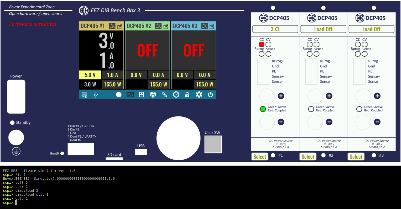
Finally, the web simulator also allows remote communication testing when SCPI commands can be tested. The terminal emulation is displayed below the image of the front panel and upon startup of the Web simulator, serial communication (via USB) will be established. Here you can test almost all SCPI commands described in the SCPI Reference manual. Few simulator-specific commands are described in Chapter 9.
In the example below, an identification string is obtained, voltage, current and connected load are set, and the output of the first channel is activated.