12. Power modules calibration
This section gives an overview of the calibration features of the power modules. Recommended calibration interval for power modules is 1 year. This will ensure that power modules remains within specification for the next calibration interval.
For optimum calibration results the following condition are recommended:
- The calibration ambient temperature is stable and between 20 °C and 30 °C.
- Ambient relative humidity is less than 80 %
- Allow a one hour warm-up with no load connected
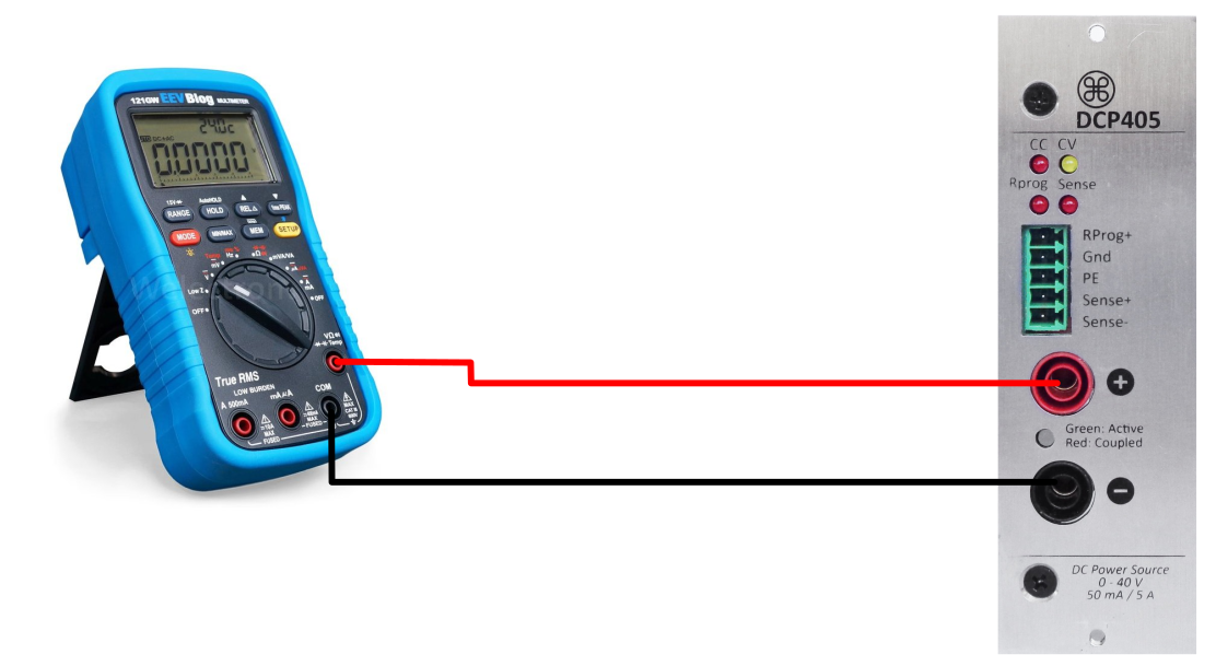
- Use short and thick cables to connect test setups
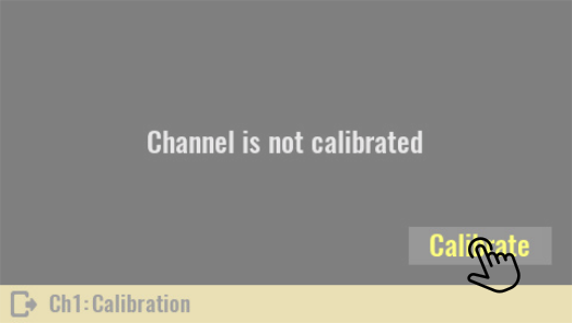
12.1. Start calibration wizardThe procedure for first calibration and subsequent recalibration is identical. If the module has not yet been calibrated or the calibration data has been deleted (using the SCPI command) the Channel is not calibrated message will be displayed.
SCPI CALibration:CLEar {<password>}
Calibration is a multistep process that results in slight adjustments to output voltage and current so that programmed and measured values are as accurate as possible. Calibration involves entering the difference between set (programmed) and measured values for at least two points within the allowable output range. The default values displayed at the start of the process can change as can the number of measuring points (up to 20). |
|
|
|
|
Only one channel can be calibrated at a time. Within the same calibration session both output voltage and current can be calibrated for the currently selected channel. The calibration procedure can be canceled at any step when entered data will be simply ignored.
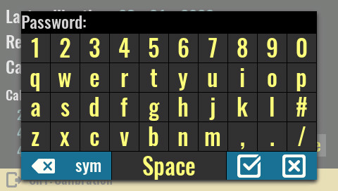
The calibration process begins by selecting the Calibrate option for the currently selected channel. The initial calibration password is eezbb3 and should not be confused with a system password that is not set by default.
SCPI CALibration ON, {<password>} |
|
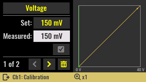
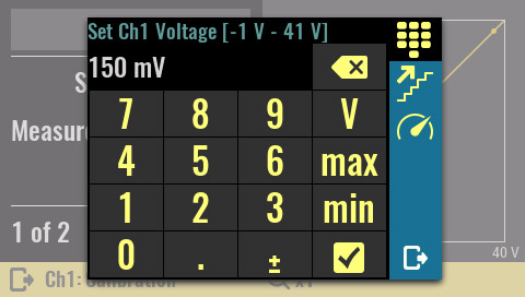
12.2.1. Voltage calibration stepsThis is the first step of the calibration procedure. The Voltage is selected for calibration, and the first voltage point is Set to 150 mV.
IMPORTANT: it is possible that module for the set 150 mV gives a voltage very close to zero or is even slightly negative. If this is the case, set the new step to e.g. 200 or even 250 mV (follow the procedure described below) that the output voltage is at least 50 mV.
|
|
|
Set: Displays output value that will be programmed for currently selected calibration point.
This value is shown for information only. Instructions for deleting or changing the total number of calibration points is described below.
Measured: The numeric keypad will be displayed by selecting this option. The value displayed on the external DMM should be entered with an arbitrary number of decimal places. Save the calibration data by selecting the Confirm icon. |
|
SCPI
CALibration:VOLTage:LEVel
|
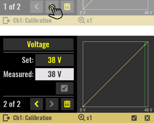
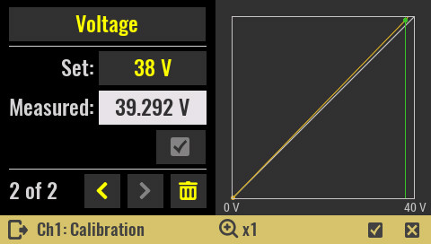
Move to the next calibration point using the right navigation icon. Measure the voltage and enter it into the Measured field. |
|
|
After each entry of the measured value for the set calibration points, it will be possible to see the change in the graph to the right, i.e. the deviation of the calibration curve (yellow) from the ideal curve (white). |
|
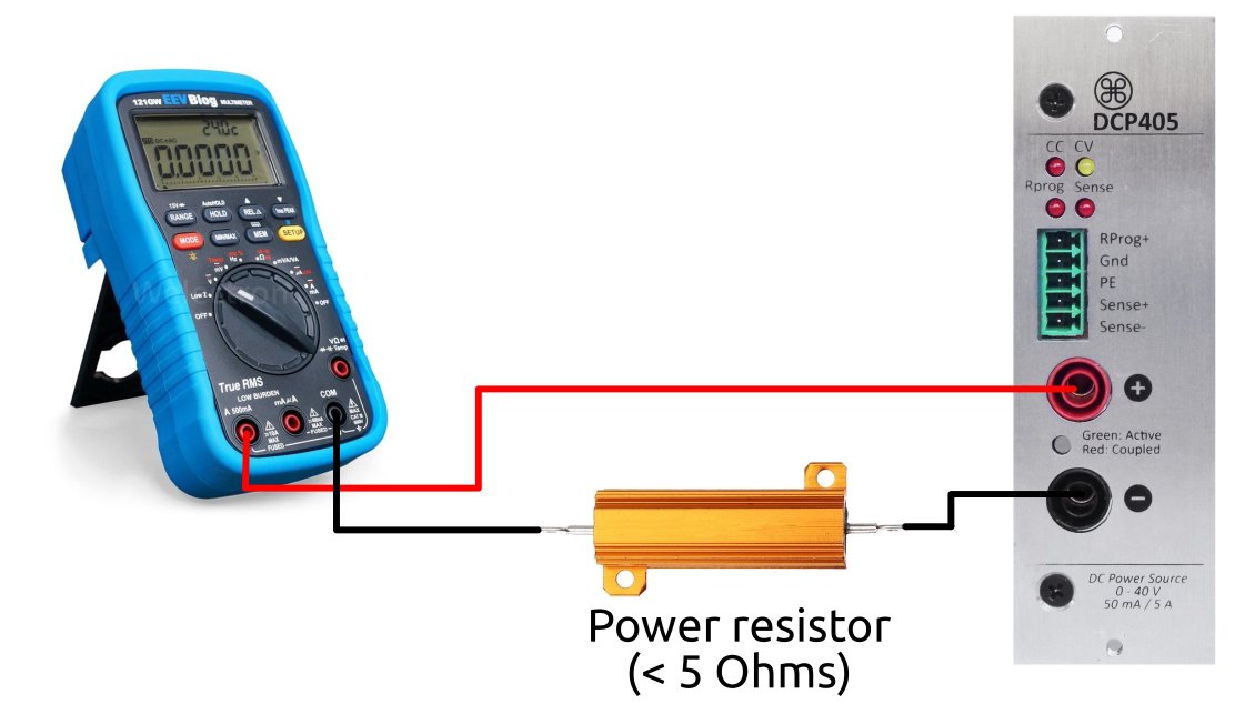
12.3. Current calibration setupFor current calibration, connect an appropriate power resistor (less then 5 Ω) in series with DMM set to current measurement. |
|
|
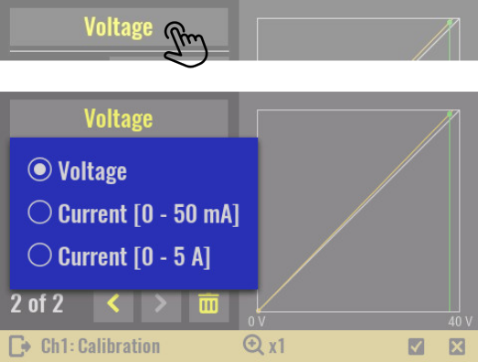
Tap on the Voltage button to open a menu from which you can select the current range.
|
|
|
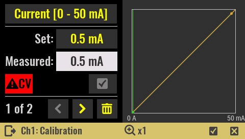
If the power resistor is of the appropriate value and properly connected, the power module will enter CC mode. Otherwise, a warning sign will be displayed that the output is still in CV mode.
|
|
|
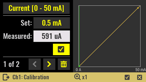
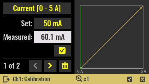
Enter the measured value for the first point and select Confirm button.
SCPI CALibration:CURrent:LEVel |
|
|
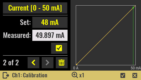
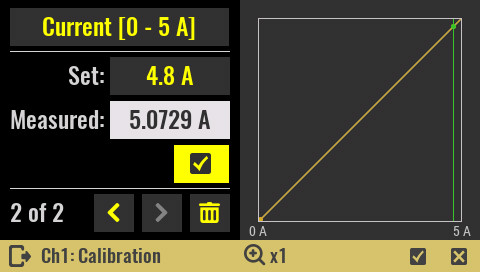
Move to the next calibration point using the right navigation icon and enter measured value for the next point and select Confirm button. |
|
|
After calibrating the low range current, repeat the same procedure for the high range and enter the measured value for the first point.
|
|
|
Once again move to the next calibration point using the right navigation icon and enter measured value for the next point.
|
|
12.3.1. Deleting existing and adding new calibration points
Any calibration point can be deleted by selecting Trash icon or new calibration point can be added by simply entering a new value in calibration point Set field. The maximum number of calibration points for any selected parameter (i.e. voltage, low range current or high range current) is 20.
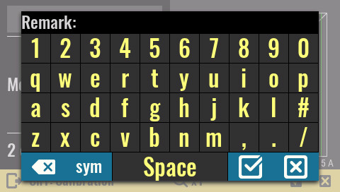
12.3.2. Save calibration parametersThe final step is to save the calibration parameters. Upon confirmation, the calibration parameters are written to non-volatile memory within the power module; calibration parameters are retained even if the power module is moved to another slot.
The last parameter that can be set during calibration is remark. The remark has two parts: |
|
SCPI CALibration:SAVE CALibration:REMark {<user remark>} |
|
|
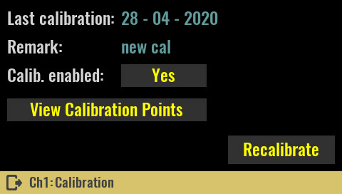
After the calibration is successfully complete the calibration information will be displayed.
Calib. enabled This option defines whether calibration parameters are used to set and readout voltage and current output values. It can only be enabled when at least one of the calibration ranges (i.e. voltage, current high or low range) is successfully stored.
SCPI CALibration:STATe ON |
|