16. Scripting with MicroPython

One of the prominent features of BB3 is support for MicroPython scripting. Thanks to MicroPython scripting it will be possible to add new functionality without intervening in the BB3 firmware and compromising its performance. Scripting opens up the possibility of creating a whole range of new applications from tasks to automate the programming of individual peripheral modules, to useful utilities such as various parameter calculators that do not require working with modules at all, but can be useful and at hand.
MicroPython is a lean and efficient implementation of the Python 3 programming language that includes a small subset of the Python standard library and is optimized to run on MCUs such as STM32 used in BB3. MicroPython aims to be as compatible with normal Python as possible to allow you to transfer code with ease from the desktop to a MCU or embedded system. For more information, visit the official micropython.org website.
This chapter will describe the procedure for creating a front-end GUI, deployment, and running a MicroPython script.
16.1. Distinctive features of BB3 MicroPython implementations
In order to avoid misunderstandings and wrong expectations, the specifics of the MicroPython implementation should be explained first.
The implementation of MicroPython often means that MicroPython will take control of all hardware resources and processes. This is not the case with BB3 and it was done on purpose. Execution of the MicroPython script takes place in a separate thread controlled by FreeRTOS and has a lower priority than the main thread that is in charge of all vital system functions. This ensures that a faulty script cannot compromise basic functionality and can be aborted from the main thread.
When the execution of the MicroPython script is complete, its thread goes to sleep until the next call.
Although the lack of direct access to hardware resources from the MicroPython script may seem like a serious limitation, access is still possible but indirectly by using a large number of implemented SCPI commands and queries that cover all important aspects of working with hardware resources of the BB3 chassis and installed peripheral modules.
For this reason, to work effectively with MicroPython scripts, it is recommended to familiarize yourself with the SCPI command set, which is described in the EEZ BB3 SCPI reference guide.
The BB3 MicroPython implementation has another distinctive feature, and that is the ability to manage user interaction via a GUI in run time using custom made pages.
The creation of new GUI pages is made possible thanks to the EEZ Studio application, which is also used to create the entire BB3 GUI for the color TFT touch-screen display.
A step-by-step procedure on how to create a simple EEZ Studio project that the MicroPython script will be able to use in run time to interact with the user will be described below.
16.2. Sample MicroPython script
As an example of using MicroPython scripting, it will be shown how to create a user form that will appear on the display and through which it will be possible to change the voltage on the first channel of the available power module. The required procedure is divided into three sections: creating an EEZ Studio project, writing a MicroPython script and MicroPython script deployment and execution.
16.2.1. Creating an EEZ Studio project
As a first step, make sure you have the latest version of EEZ Studio, which you can download at https://github.com/eez-open/studio/releases and install it on your computer.
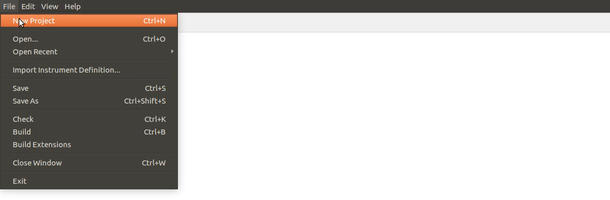
Fig. 1: Open new project
Start EEZ Studio and select the New Project option from the File menu (Fig. 1). A new window will open displaying the Setting general page as shown in Fig. 2.
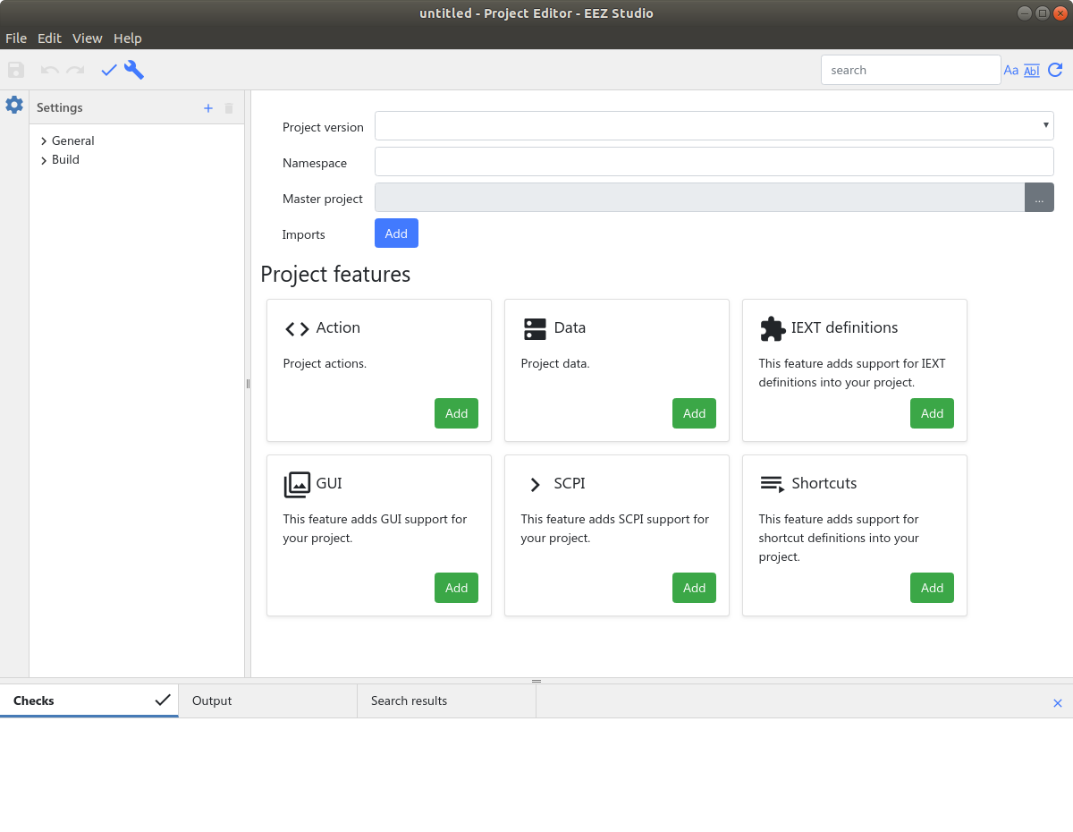
Fig. 2: Newly added project Settings general page
General settings contain the following parameters that will need to be defined:
- Project version – project version number
- Namespace – not currently used
- Master project – path to EEZ BB3 master firmware project
- Project features – determines which features will be used in the project.
Before you define the general parameters of the project, first save it to the desired destination. The extension of the EEZ Studio project is .eez-project and Linux users need to enter the name and extension when saving, in our case it will be Hello World.eez-project. When a project is saved its name will appear instead of untitled in the window header.
Now we can define the version of the project, which should be V2. Next, define the path to the master firmware of the project, i.e. to modular-psu-firmware.eez-project which can be found at the following link: https://github.com/eez-open/modular-psu-firmware/blob/master/modular-psu-firmware.eez-project. The easiest way is to copy the master project to the folder where the saved and newly created project is located. Access to the master project is required in order to gain access to styles, color themes and fonts so that the page we will create is in line with other content on the screen.
It remains to define the Project features that will be used to interact via the TFT touch-screen display. Since such interaction is based on the event-driven principle it will be necessary to define the following: GUI layout, allowed actions and data to be exchanged during the action (event). Therefore we need to choose (using Add button) the following three features: GUI, Action and Data.
If we have well defined all the above parameters, the General settings page will look like in Fig. 3.
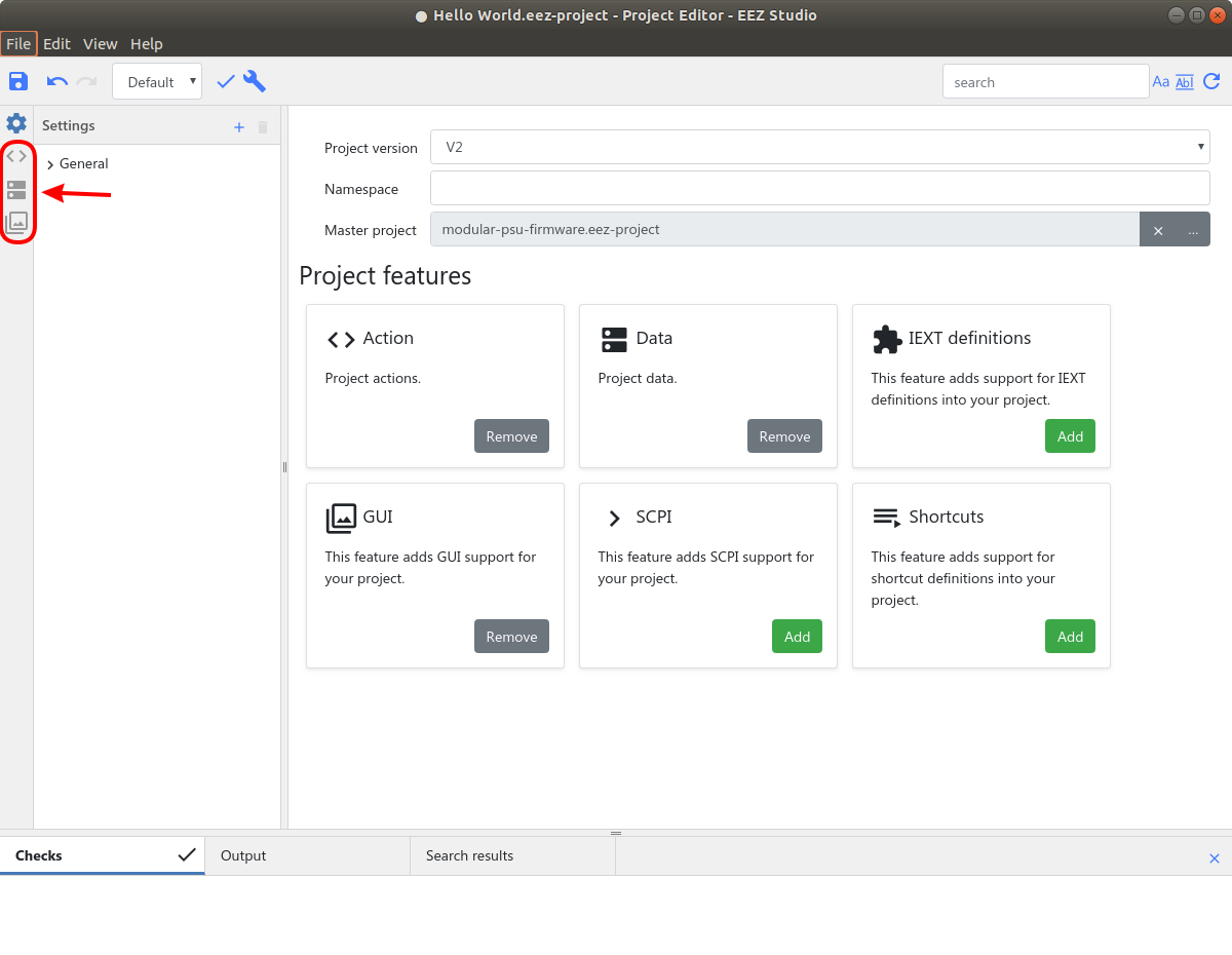
Fig. 3: General settings page with defined project parameters
Note that each of the selected Project features has added a new tab on the left side through which it will be possible to access the parameters of the selected feature.
To get the functional page that will be called from the MicroPython script it will be necessary to define the parameters via these three tabs that have appeared.
We will first define the names of the actions. For example, input_voltage to enter the desired output voltage, set_voltage to set the output voltage and close to close the page and stop execution of the MicroPython script. Use the + option to add all above mentioned actions by name, and leave default values of the other action parameters (i.e. Description and Used in). Once the action list is added it should look like in Fig. 4.
Fig. 4: List of defined actions
In the next tab we will define the data to be used for the actions. A minimum of three parameters will need to be defined for each data: name, type, and default value. These will be can_set_voltage as Boolean, default 0 (false) and voltage as Float, default 3.0 V. The default value will appear in the GUI item when it is assigned a specific data. Properties of both data are shown in Fig. 5.
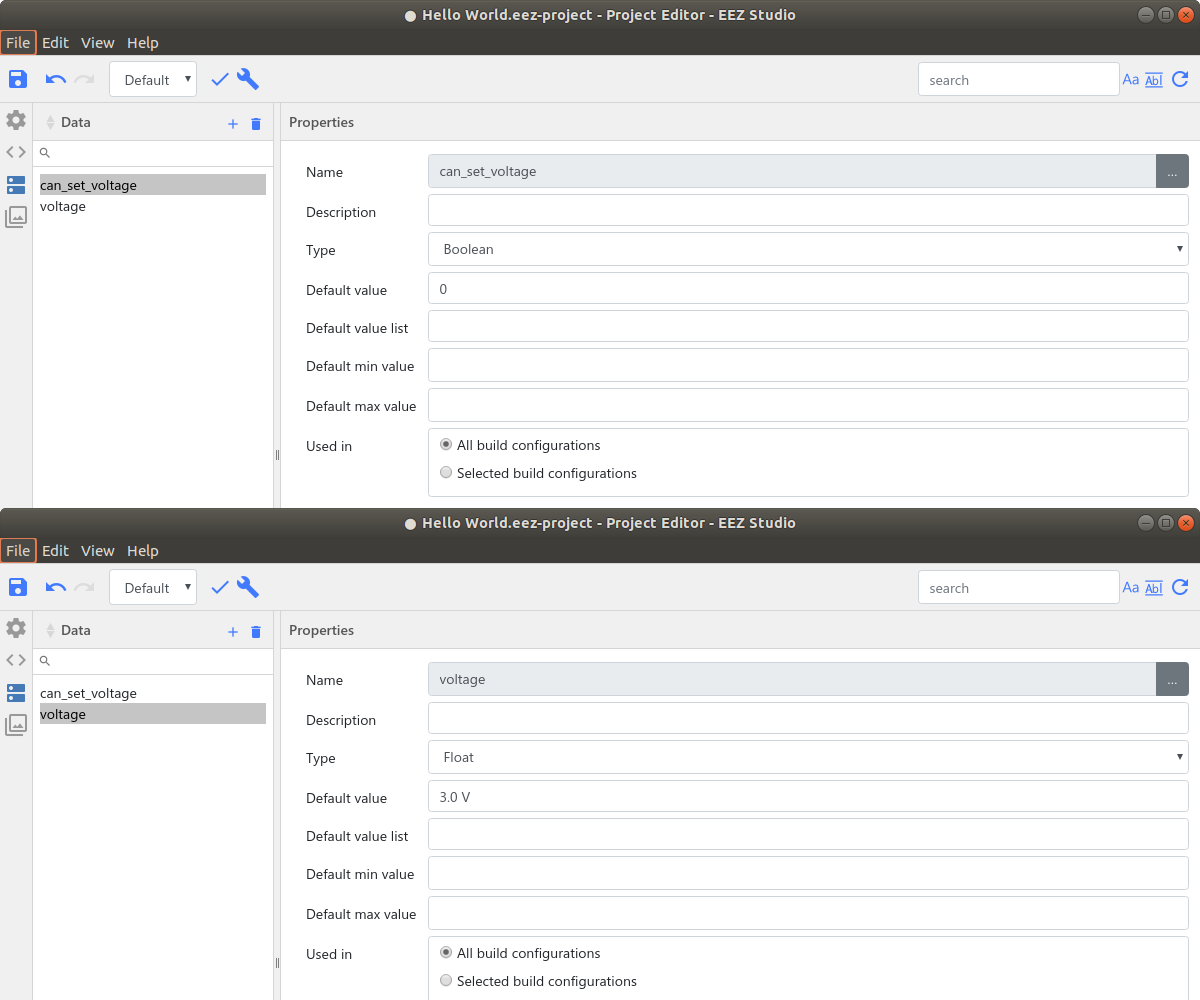
Fig. 5: Defined project data
The GUI section is the most complex and before describing the creation of the page, it is necessary to explain what it contains. The section without any defined page is shown in Fig. 6.
This section is divided into two subsections: Pages (Layouts) and Bitmaps which have corresponding tab icons. In our example, we will not use bitmaps, so that subsection will not be described.
This section can also contain other subsections such as Fonts and Styles, however in our example this is not applicable because we chose to inherit the fonts and styles from the master project.
Pages (Layouts) consists of the following sections:
- Pages (Layouts) – a list of names of defined pages
- Page structure – the tree structure of all widgets used. It can be used to quickly move widgets within a structure
- Page preview – a central space that has no title, and will get a tab with the name of the page for each selected page. It displays selected page widgets and can be used to select and move one or more selected widgets
- Properties – displays all parameters of the selected widget
- Widget palette – a menu with all currently implemented widgets. In our example, we will use the two most commonly used widgets: Container and Text.
- Themes – color theme list. In our example they are inherited from the master project
The procedure for defining a page is as follows: add a new page, insert the necessary widgets, and assign actions and data to the widgets as needed. We will add a new page using the + option in the Pages (Layouts) section.
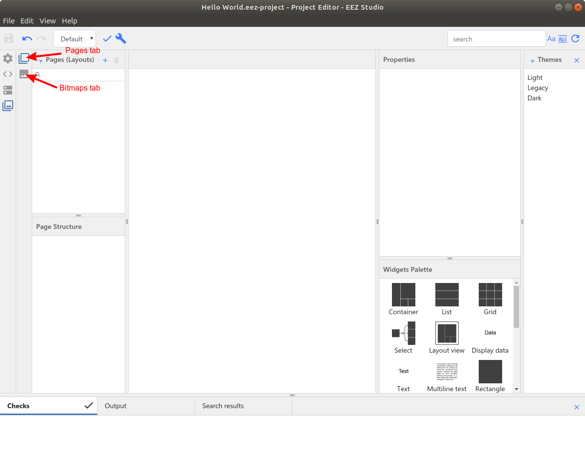
Fig. : Empty GUI feature section
The new items Page will appear and its Properties will be displayed. This will look like Fig. 7 (Checks and Themes sections are minimized for a simplified view). In Properties we can also see that the name is Page and we can change it to something else, say Main for which we will use […] button at the right of the Name field.
We can now start inserting the widgets one by one. To do this, select the widget from the Widgets palette and drag & drop it to the central section (it may or may not be inside the page area since the final coordinates will be defined later).
As the first widget we will take one Container which, as its name suggests, is used to contain several other widgets (including other containers) which simplify the organization of widgets and their manipulation.
The container may or may not have a defined name, and for its size and position we will use Position and size properties, so we will set:
- Width – 204
- Height – 90
- Left – 138, if we want a container of these dimensions to appear in the middle, but we can also enter here equation like (480 - 204) / 2 since these fields accept basic mathematical operations (480 because it is the width of the page, 204 because it is the chosen width of the container and we divide by 2 to center it).
- Top – 75
Note that the Pin to edge, Fix size and Preview options are intended for automatic positioning and have not yet been implemented.
We will add a few widgets to this container. Adding a widget to an existing container can be done by dragging it in the desired container into the Page structure tree on the left. When positioning inside a tree structure, make sure that the purple marker is indented under the container to which you want the widget to belong (see Fig. 9).
If no container is created, you can select one or more of existing widgets and insert it into the new container that will be created on that occasion. To do this, use the Put in container option from the right mouse button menu.
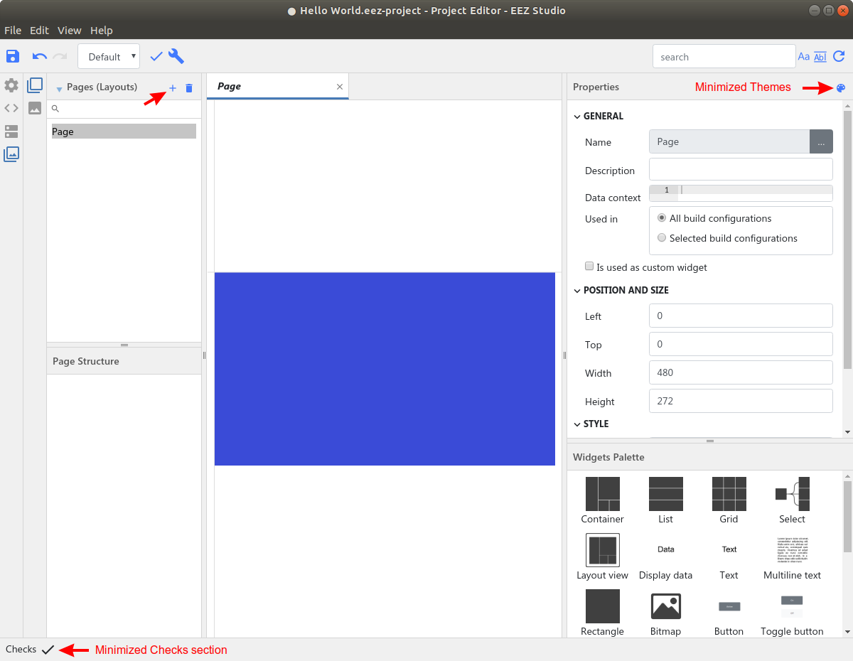
Fig. : Newly created GUI page
We will add the following widgets to the same container:
- Text – Left: 0, Top: 0, Width: 84, Height: 40 (Absolute position will become 138, 75)
- Text – Left: 84, Top: 0, Width: 120, Height: 40 (Absolute position will become 222, 75)
- Button – Left: 84, Top: 50, Width: 120, Height: 40 (Absolute position will become 222, 125)
In addition, we will create another container that will define the status line in which the exit option will appear, for this we will need:
- Container – Name: Status line, Left: 0, Top: 240, Width: 480, Height: 32 (Absolute position will become 0, 240)
- Text – Left: 0, Top: 0, Width: 41, Height: 32 (Absolute position will become 0, 240)
- Text – Left: 41, Top: 0, Width: 439, Height: 32 (Absolute position will become 41, 240)
In the next step, we can define additional widget properties: their Style (i.e. fonts and colors) and Specific properties. Since we have chosen to inherit styles from the master project, only the styles defined there as exportable (i.e. have a defined Id in properties) will be available when […] button is selected to the right of the Normal style input field. A new window will then open with a list of all available styles as shown in Fig. 10.
Using this option for widgets from the first container we will set the following:
- Text – Normal style: default_M_left, Text: Voltage:
- Text – Normal style: edit_value_active_S_center, Text: (change to blank). The Text property can be left filled with default value (i.e. Text), but in that case the default value of the data that we will associate with that widget (3.0 V) will not be displayed on the page.
- Button – Normal style: button_M, Disabled style: button_M_disabled, Text: Set
For the widgets from the 2nd container we will set the following:
- Text – Normal style: status_icon_enabled, Text: E (please note that this style uses an icon font so the letter E is used because the Exit icon corresponds to that position)
- Text – Normal style: status_title, Text: Hello World
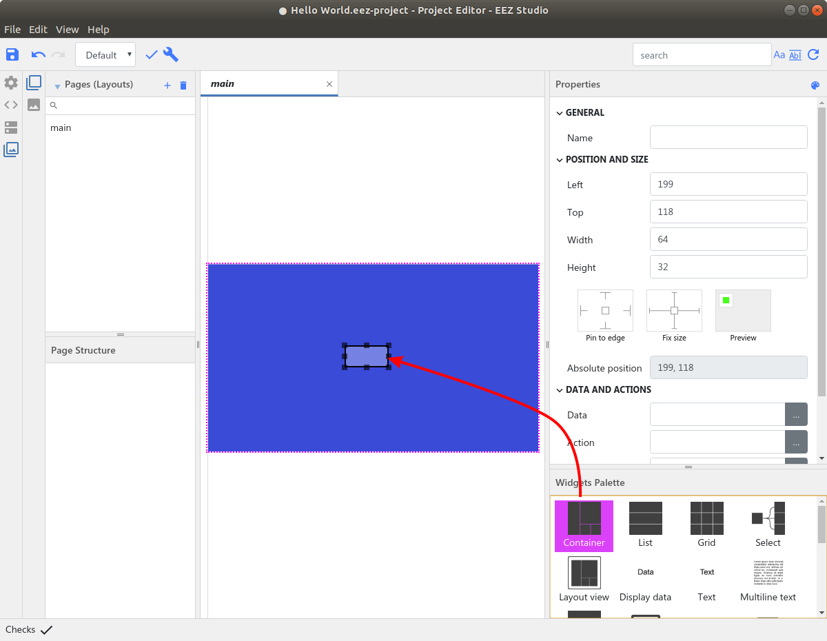
Fig. : Adding container widget
If you have done well so far you should have a fully defined page as shown in Fig. 11. It remains to set the action and data on certain widgets which we will do in the next step.
First container:
- Voltage: text widget is informative, and no action is expected on it. Therefore, its Data and Action fields should be left blank.
- The second text widget will be used to display the existing voltage and set the new voltage value at the CH1 output. For this reason, we will choose voltage for Data, and input_voltage for the Action, which we defined at the very beginning. To select Data and Action, we will use the corresponding […] options to the right of the Data and actions properties input fields.
- We will use the Set button widget to confirm the entry and execute the part of the MicroPython script that will set the entered value. We leave the Data blank. As Action we choose set_voltage. This widget has another additional action property and that is Enabled. If there is a criterion during the execution of the MicroPython script that the button is enabled, we will be able to touch it, for which we will select the can_set_voltage from list of actions.
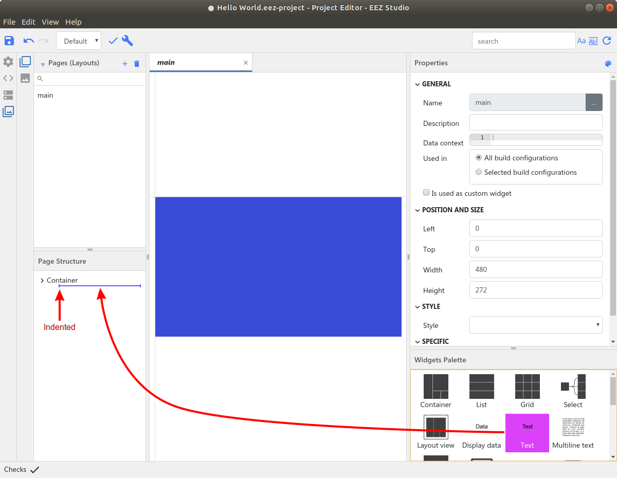
Fig. : Inserting new widget into container
Second container:
- The E text widget will be used to return from this page to the main page, which also means stopping further execution of the MicroPython script so the output voltage will not be set to the new value. For this reason, we will select here close as Action. Data field should be left blank.
- Hello world text widget is informative, and no action is expected on it. Therefore, its Data and Action fields should be left blank.
This completes the creation of the page to be used to interact with the MicroPython script. All we have to do is write a MicroPython script and deployment to BB3 which will be described below.
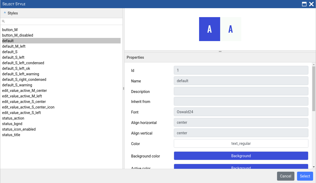
Fig. : Inherited Styles selection
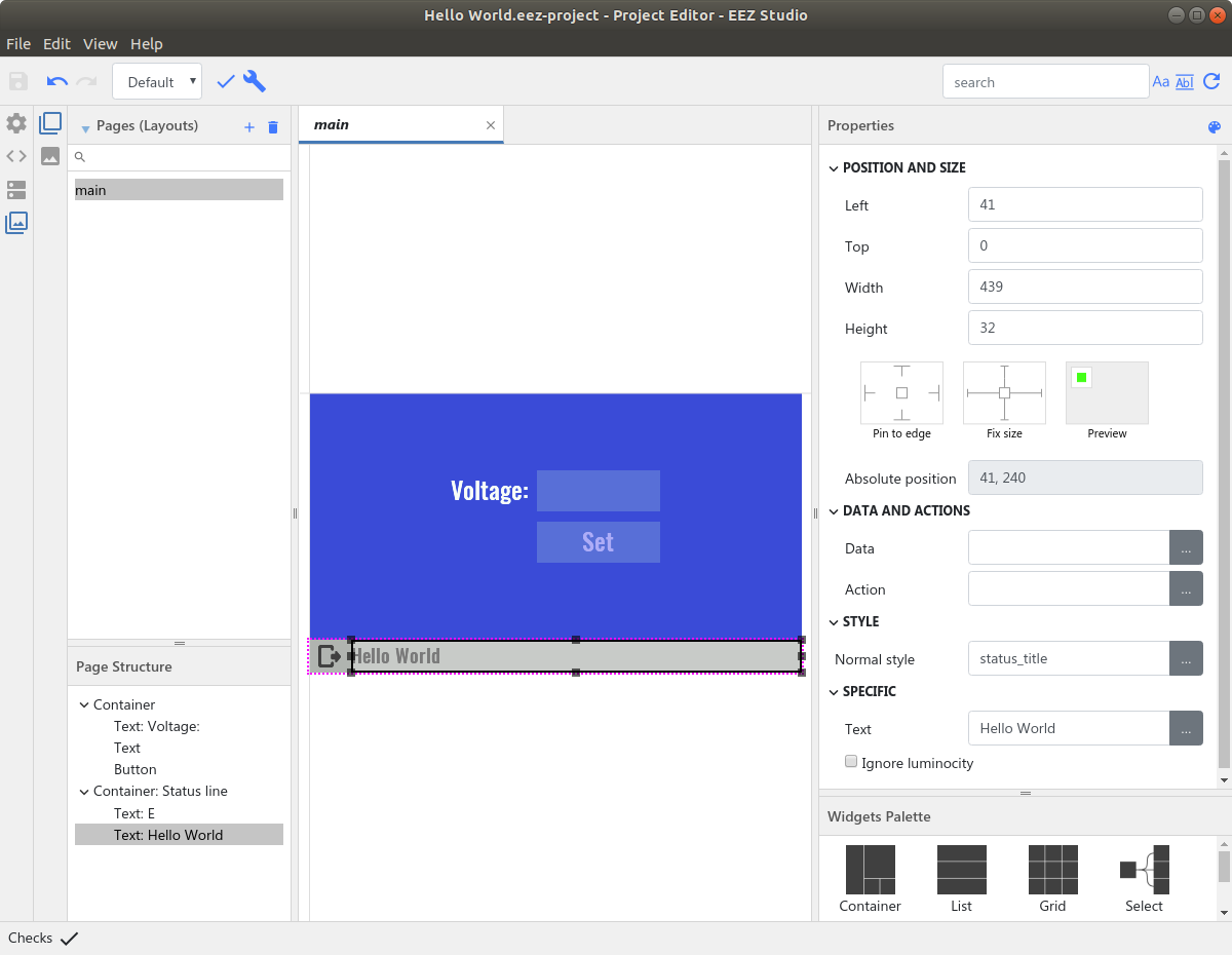
Fig. : Page view with all widgets and defined styles
16.2.2. MicroPython script
EEZ Studio does not currently offer the creation and editing of text files. Therefore, you can use your favorite text editor to write the MicroPython script listed below. The name of the MicroPython file should be Hello world.py to match the name of the EEZ Studio project.
|
Code |
Explanation |
|
# Hello, World!
|
The text that will appear as a description of the MicroPython script when displayed on BB3 (see File manager section). |
|
from eez import scpi
|
Include scpi function from eez module |
|
def input_voltage(): global voltage, max_voltage value = scpi(‘DISP:INPUT? "",NUMBER,VOLT,0.0,’ + str(max_voltage) + ‘.0,’ + str(voltage)) |
This is the implementation of the input_voltage action defined in the EEZ studio project. When one click on the voltage widget this function will be launched.
The SCPI command DIAG:INPUT? opens the input dialog on the screen where voltage can be entered. |
|
if value != None: voltage = float(value) scpi(‘DISP:DIALog:DATA "voltage",FLOAT,VOLT,’ + str(voltage)) scpi(‘DISP:DIALog:DATA "can_set_voltage",INT,1’)
|
If voltage is entered then two data items are set: voltage to the entered value and can_set_voltage to 1 which means that voltage is entered and can be set on the channel, which results in the Set button widget being enabled. |
|
def set_voltage(): scpi("INST ch1") scpi("VOLT " + str(voltage))
|
Select CH1 as set its output voltage. |
|
def main(): global voltage, max_voltage scpi("INST ch1") voltage = scpi("VOLT?") max_voltage = scpi("VOLT? MAX") |
Main program loop. SCPI command INST is used to select CH1 on power module and two SCPI queries that return currently set voltage (VOLT?) and max allowed voltage (VOLT? MAX). |
|
scpi("DISP:DIAL:OPEN \"/Scripts/Hello World.res\"") |
Invoke Hello World.res file using the DISP:DIAL:OPEN that contains page created in EEZ Studio as discussed above. |
|
try: scpi(‘DISP:DIAL:DATA "voltage",FLOAT,VOLT,’ + str(voltage))
while True: action = scpi("DISP:DIALog:ACTIon?") if action == "input_voltage": input_voltage() elif action == "set_voltage": set_voltage() break elif action == "close" or action == 0: break |
This is a dispatcher that asks via the SCPI command DISP:DIALOG:ACTION? which action the GUI requires to be performed. The dispatcher is executed in a loop: when it receives from the GUI which action to perform, it executes it and asks again what the next action is. If the detected action is close or 0 (this means that the firmware has requested closing the dialog) then the dispatcher loop is broken and goes to finally section described below. |
|
finally: scpi("DISP:DIAL:CLOS")
main() |
Execute SCPI command DISP:DIAL:CLOS to close last dialog window opened with the DISP:DIAL:OPEN command. This section will be also executed in case of an error, i.e. exception. |
16.2.3. MicroPython script deployment and execution
Once we are done with the EEZ Studio project and the MicroPython script we are ready for deployment. In order for the page created in EEZ Studio to be used successfully on BB3, it must not contain any errors and should be "compiled". The Check and Build options are used for this, and Fig. 12. shows the result of the Build action in the Output tab. It will create in the same folder where the EEZ Studio project resource file Hello world.res.
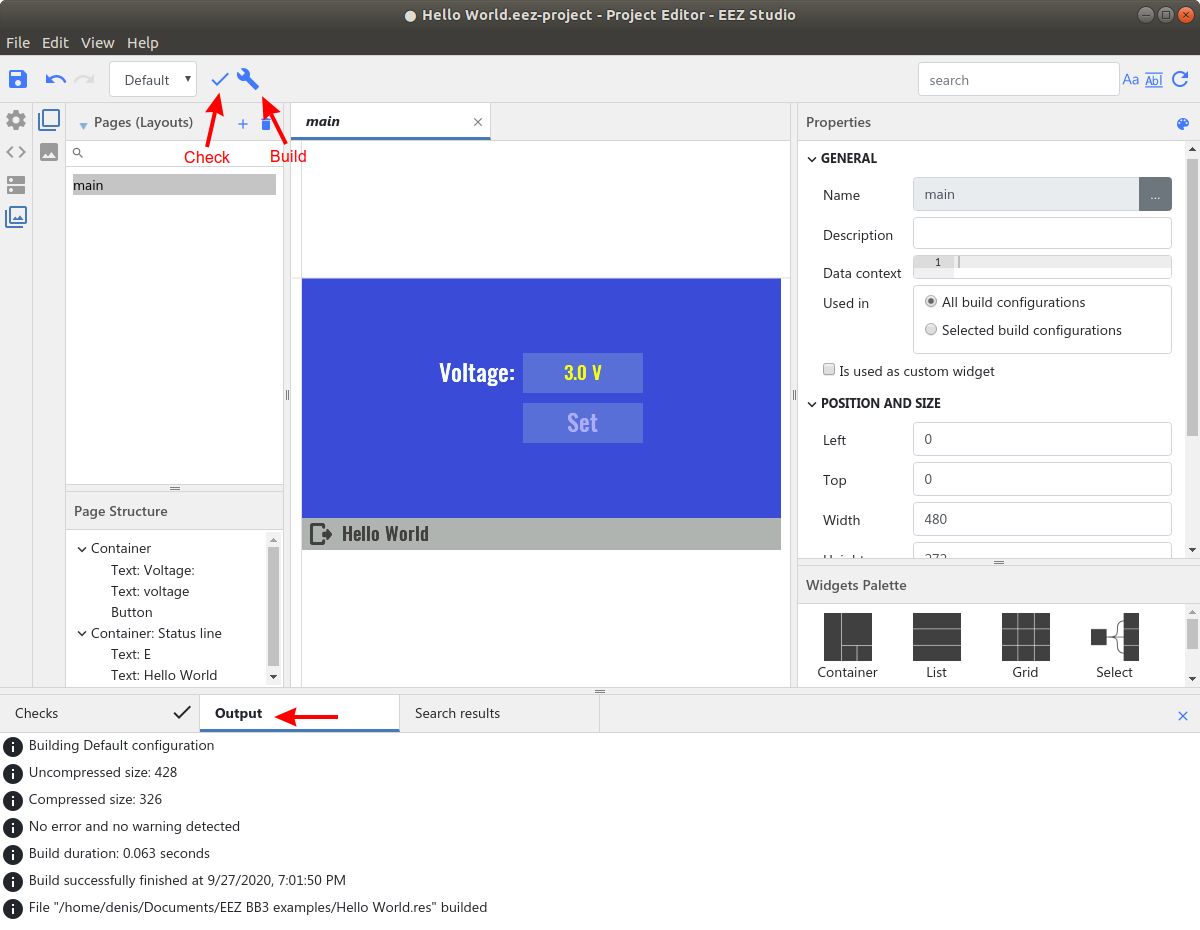
Fig. : EEZ Studio project Check and Build options
Hello world.py and Hello world.res files will now need to be downloaded to BB3 in the Scripts folder. We can also use EEZ Studio for this, but its ESW part used to communicate with SCPI instruments such as BB3. The procedure is the same as in the case of the Upgrade peripheral module firmware using GUI on BB3 section in Chapter 13. The download parameters of the MicroPython script are shown in Fig. 13. The same will need to be done for the resource file (Hello world.res ).
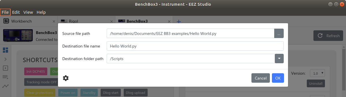
Fig. : File transfer using EEZ Studio Send File option
During execution, if the MicroPython script has an error, a message will appear as in Fig. 14. The show debug trace log option leads to the event log viewer where more details about the error can be found (Fig. 15).
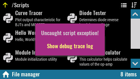
Fig. : MicroPython script error message
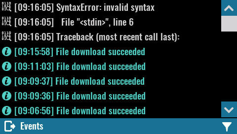
Fig. : MicroPython script error details in event log
The current implementation does not offer a script debugger or the ability to modify the script on the BB3 side. During development, all MicroPython script modifications will need to be made to the computer side and the changes will need to be downloaded as previously shown.
16.3. EEZ Python module
In our example the MicroPython script used eez module. The table below contains the names and descriptions of all the functions that the module contains. The current version of the module can be found at:
For MicroPython references visit: http://docs.micropython.org/en/latest/reference/index.html
A list of currently implemented / enabled functions in BB3 firmware can be found at this link:
|
Function name |
Description |
|
eez.scpi(commandOrQuery) |
Execute any SCPI command or query. If command is executed, then None is returned. If query is executed, then it returns query result as integer or string. |
|
eez.getU(channelIndex) |
Returns measured voltage as float for the given channel index.
This is the same as MEASure[:SCALar]:VOLTage[:DC]? query. Use this function instead of SCPI query when performance requirement is critical. |
|
eez.setU(channelIndex, currentLevel) |
This function sets the immediate voltage level for the given channel index.
It is equal to [SOURce[<n>]]:VOLTage[:LEVel][:IMMediate][:AMPLitude] command. Use this function instead of SCPI command when performance requirement is critical. |
|
eez.getI(channelIndex) |
Returns measured current as float for the given channel index.
This is the same as MEASure[:SCALar]:CURRent[:DC]? query. Use this function instead of SCPI query when performance requirement is critical. |
|
eez.setI(channelIndex, currentLevel) |
This function sets the immediate current level for the given channel index.
This is the same as [SOURce[<n>]]:CURRent[:LEVel][:IMMediate][:AMPLitude] command. Use this function instead of SCPI command when performance requirement is critical. |
|
eez.getOutputMode(channelIndex) |
For the given channel index, returns:
This is the same as OUTPut:MODE? query. Use this function instead of SCPI query when performance requirement is critical. |
|
eez.dlogTraceData(value, …) |
For current DLOG trace file, this function adds one point in time for each defined Y-axis. It expects one or more value arguments depending of how much Y-axis values are defined for currently started DLOG trace.
This is the same as SENSe:DLOG:TRACe[:DATA] command. Use this function instead of SCPI command when performance requirement is critical. |
16.4. MicroPython script examples
EEZ Studio communicates with SCPI instruments using the so-called IEXT (Instrument EXTension). IEXT for BB3 includes, among other things, several MicroPython scripts that can be easily transferred to BB3, as well as later updated if newer versions of BB3 IEXT include changes to MicroPython scripts. EEZ Studio projects and MicroPython scripts can be found at https://github.com/eez-open/modular-psu-firmware/tree/master/scripts
|
Script name |
Description |
|
Curve Tracer |
Plot output characteristic for BJTs and MOSFETs |
|
Diode Tester |
Determines diode reverse breakdown voltage |
|
Hello World |
The script used in the example previously described in this chapter |
|
Module Initialization |
EEZ peripheral module initialization utility |
|
Op-Amp Calculator |
This calculator helps calculate values of the op-amp configured as inverting, non-inverting or differential amplifier |
|
Parallel and Series Calculator |
Calculates parallel resistance/inductance or capacitance is series |
|
Voltage Divider Calculator |
This calculator helps calculate values of resistive voltage divider |