How To – Deliver the right voltage/power to the load with remote sensing
How To – Deliver the right voltage/power to the load with remote sensing
|
Estimated reading time: 5 minutes |
|
Remote sensing is widely used for example in telecommunication applications to meet the demanding accuracy requirements of critical ASICs and processors. When a load draws a high current, the voltage drop across the power leads could be high enough to cause a device under test (DUT) to fail or cause a system to malfunction. The solution to this problem is to use remote sensing.
Remote sensing is a feature on DCP405 power module that allows it to remotely regulate the voltage right at your load. This is accomplished by using a set of remote sense leads that are in addition to your load leads. The DCP405 uses the voltage on the remote sense lead terminals to sense the voltage right at the load terminals and regulate the voltage right at the load by adjusting the output terminal voltage.
Using remote sense will have an impact on regulation performance, which should be considered along with the benefit of compensating for the voltage drop in your leads.
How big the voltage drop across the cables can be? For currents of a few amperes even with a thick cable it can be significant: in the range of a few hundred mV. When DUT is e.g. a Power-over-Ethernet device running on a 44 V nominal supply voltage, it can tolerate a few hundred mV of drop in each load lead, but when DUT is a cell phone running on a 3.6 V battery or an FPGA running at 1.1 V, even a voltage drop of few tens of mV in each load lead could result with erratic behavior since there is not enough voltage for proper operation. As nominal supply voltages drop, currents rise, causing the voltage drop through the load leads to be even higher.
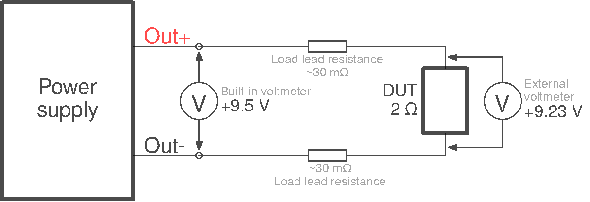
Fig. 1: Connect the DUT to a power source using remote sensing
Take for example a 2 Ω DUT that we want to supply with 9.5 V. According to Ohm’s law the expected current will be 4.75 A. However, when we connect the DUT at its terminals we can measure only 9.23 V: voltage drop of 270 mV. Consequently, we can measure that the current is not the expected 4.75 A but lower. Why? Because the resistance of the connecting cables must be added to the resistance of the DUT. If the measured current is 4.6 A then the total resistance of the connecting cables is about 59 mΩ (i.e. 0.27 V / 4.6 A).
So, regardless of the fact that some power supply may have a very precise output voltage setting down to 1 mV it will only be valid at its power terminals without any DUT connected. Thus, a power supply that would have a much coarser voltage setting with remote sensing will outperform a significantly more accurate model without a remote sensing capability.
Is increasing the power source output voltage a real alternative to this problem? It will depend on the type of DUT: if it is a static DUT whose current does not vary then it is acceptable, however for a dynamic DUT it could be dangerous because in the period of lower consumption the increased voltage could be above the allowed tolerances.
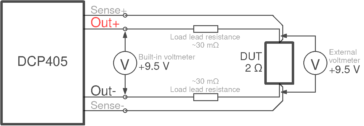
Fig. 2: Connect the DUT to a power source using remote sensing
To overcome this problem it is necessary to use a power source that has remote sensing. The connection diagram is shown in Fig. 2.
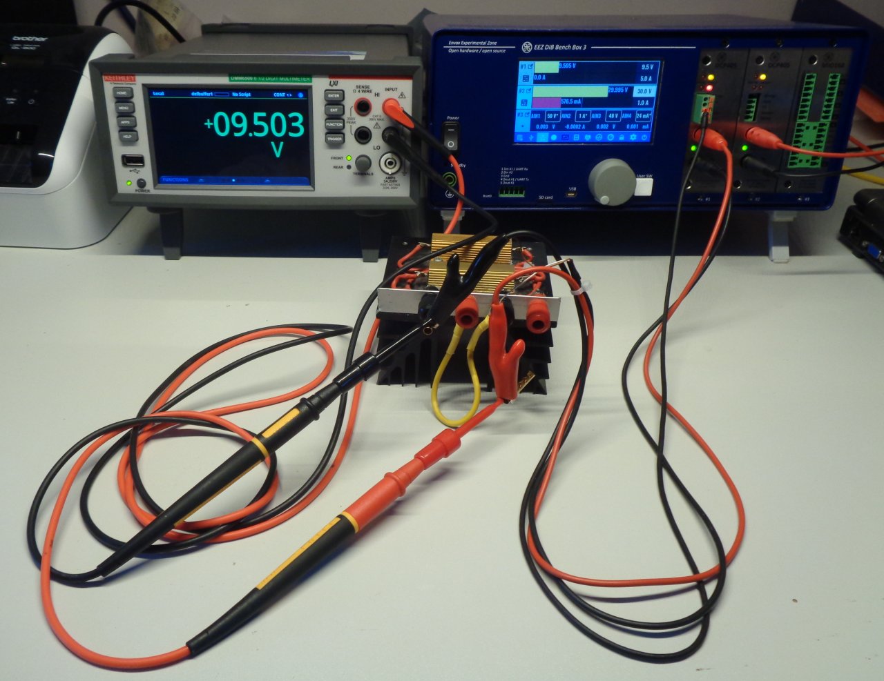
Fig. 3: Output voltage without load connected
To check this in practice we will first measure with an external voltmeter which is the voltage at the ends of the power cable without a connected DUT (Fig. 3). The measured voltage corresponds to the set voltage.
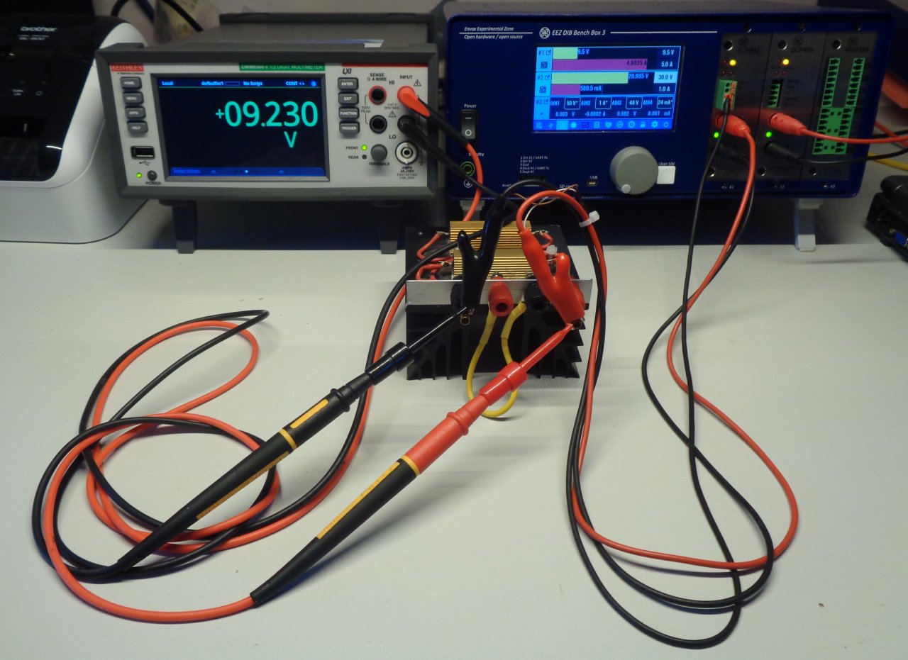
Fig. 4: Output voltage under load with Rsense off
In the next step, we will measure the voltage on the connected DUT without remote sensing. The voltage drop is significant: measured voltage is 9.23 V. For the same reason, the current is not as expected, 4.6 A was measured.
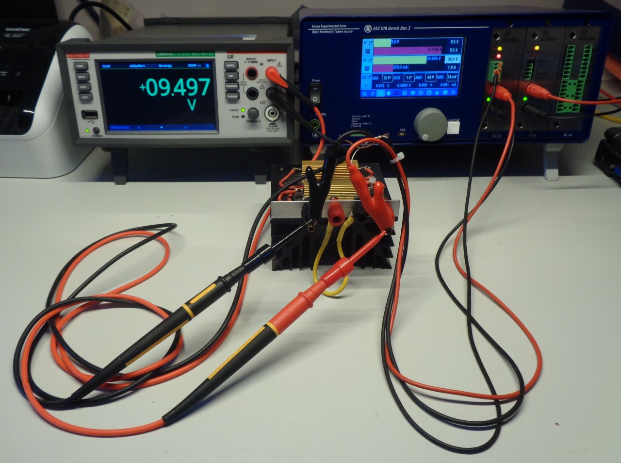
Fig. 5: Output voltage under load with Rsense on
Although the remote sensing cable is plugged in, the remote sensing will not work until it is activated via the display or the SCPI command (see Advanced options). A signal relay is used for this, and sense inputs also have reverse polarity protection.
When remote sensing is activated we can measure almost identical voltage to that without DUT connected (Fig. 5). A negligible difference of several mV occurs because the power and sense lines are not exactly at the same point.
Remote sensing wiring
To minimize noise pickup or radiation from load circuits, power leads and remote sense wires should be shielded, twisted pair cables that are as short as possible. Using twisted pair cables not only helps prevent noise pickup, but it also reduces coupling between the power leads and sense lines. Shielding of the sense leads may be necessary in high noise environments.
Another important thing is how the ends of the power and sense cables are connected to the DUT terminals. In order to keep the error between the set and delivered voltage as small as possible, the so-called Kelvin connection so that the sense terminals are not on the power path which will lead to a voltage drop and thus setting a lower than desired voltage.
In practice, this is often done with a clamp with two isolated arms so that the power is connected on one arm and the sense wire on the other.
Fig. 6. and 7. show the cable design used in this test. Figures 1 and 2 show the cable design used in this test. The ends of the power and sense cables go to the clamp. However both are on the same arm. The connection point of the sense cable is slightly offset from the connection point of the power cable towards the end of the clip.
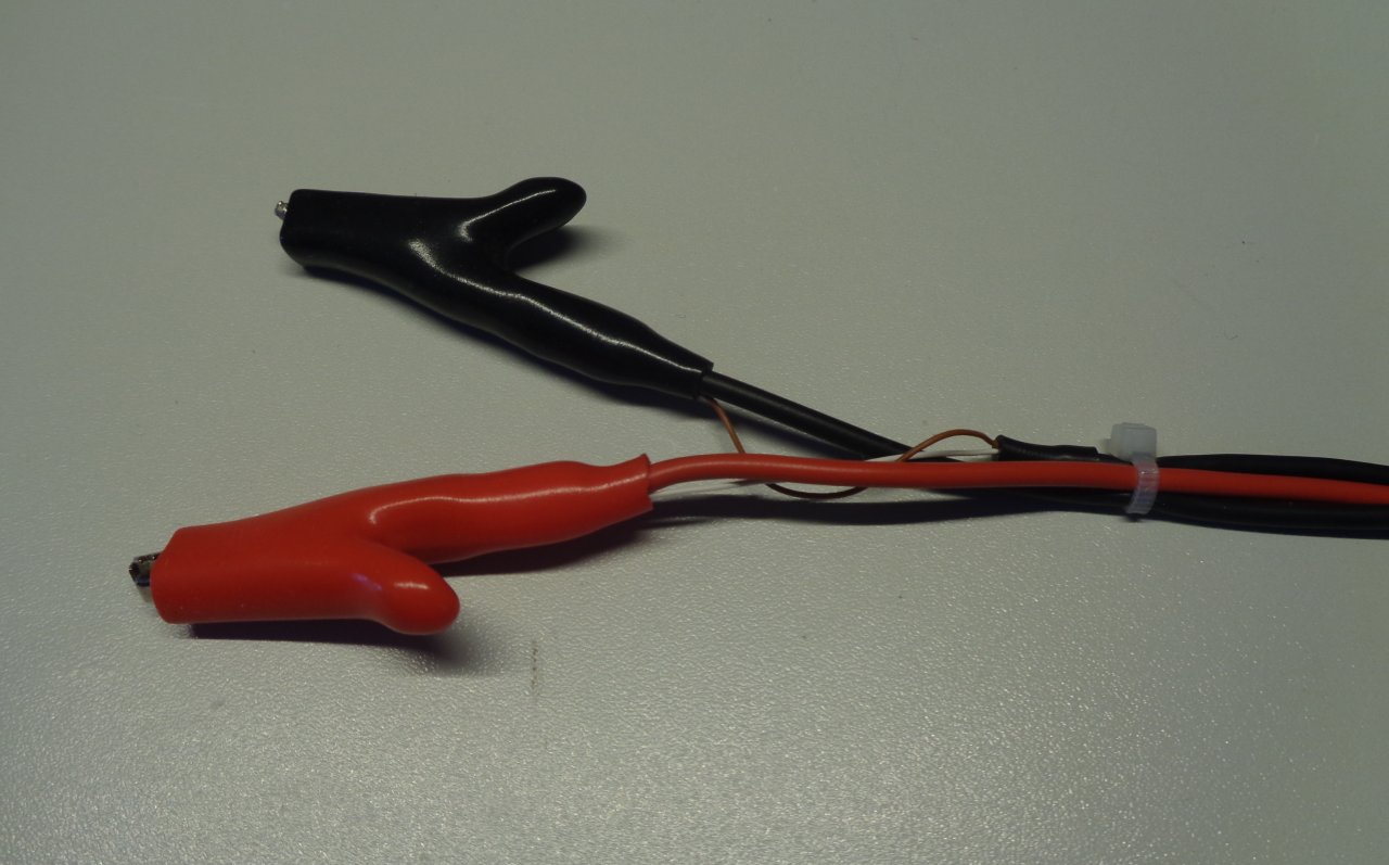
Fig. 6: 4-wire (Kelvin) clip for remote sensing
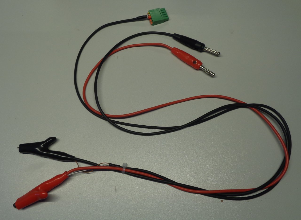
Fig. 7: BB3 power cable with remote sensing