10. Programming examples
10.1. Set channel output values and working with the OCP
This is a SCPI commands sequence that sets a voltage, current, and the over-current protection (OCP) on the channel two:
|
INST? |
Check currently selected output. |
|
1 |
|
|
INST CH2 |
Select channel two as current channel. |
|
VOLT 10 |
Set output voltage. |
|
CURR |
Set output current. |
|
CURR:PROT:STAT? |
Check OCP status. |
|
0 |
|
|
CURR:PROT:STAT 1 |
Enable OCP. |
|
CURR:PROT:DEL 10ms |
Set OCP delay. |
|
OUTP 1 |
Enable output. |
|
MEAS? |
Measure output voltage. |
|
10.00 |
|
|
MEAS:CURR? |
Measure output current. |
|
0.00 |
Current is zero since no load is connected. |
If software simulator is used, connection of the load can be also simulated:
|
SIMU:LOAD 20 |
Define connected load impedance. |
|
MEAS? |
Measure voltage once again. |
|
10.00 |
|
|
MEAS:CURR? |
Measure current once again. |
|
0.50 |
Measured current. |
The following command sequence could be used to test channel mode with load previously defined and after the load impedance is lowered enough that output current reach programmed value. The OCP has to be disabled because previously defined 100 ms delay does not give us enough time to execute the whole sequence for testing channel mode and output voltage and current values:
|
OUTP:MODE? |
Check mode of operation. |
|
"CV" |
The channel is in constant-voltage mode since output current is below previously programmed level. |
|
SIMU:LOAD? |
Check load value. |
|
10 |
|
|
CURR:PROT:STAT? |
Check OCP status. |
|
1 |
|
|
CURR:PROT:STAT OFF |
Disable OCP. |
|
SIMU:LOAD 4 |
Decrease load impedance. |
|
OUTP:MODE? |
Check once again mode of operation. |
|
"CC" |
Channel enters constant-current mode since Imax = U / R = 10 / 4 = 2.5 A and current is limited to the 1 A. |
|
MEAS:CURR? |
Measure output current. |
|
1.00 |
|
|
MEAS? |
Measure output voltage. |
|
4.00 |
Output voltage is decreased since U = I * R = 1 * 4 = 4 V. |
The OCP will “trip” when output current reach programmed value and channel stay in the CC mode for more then programmed OCP delay time. To test that with e.g. the software simulator we’ll disable channel output first, enable OCP and when change channel output back to enabled state:
|
OUTP OFF |
Disable channel output. |
|
CURR:PROT:TRIP? |
Check OCP status. |
|
0 |
OCP is not activated. |
|
CURR:PROT:STAT ON |
Enable OCP. |
|
VOLT? |
Check programmed output voltage. |
|
10.00 |
|
|
CURR? |
Check programmed output current. |
|
1.00 |
|
|
SIMU:LOAD? |
Check simulated load value. |
|
4 |
|
|
OUTP ON |
Enable channel output. |
|
CURR:PROT:TRIP? |
Check OCP status once again. |
|
1 |
OCP has been tripped. |
|
OUTP? |
Check channel output state. |
|
0 |
Channel output is changed to OFF stated by the OCP. |
The channel output state cannot be changed to enabled until any of protection is active. We have to clear protection first. If the same load that caused the first protection trip is still connected the channel output will be disabled immediately after the protection programmed delay time expired. Therefore we also have to disconnect load or disable protection. The later method will be used in the command sequence that follows:
|
OUTP ON |
First attempt to enable channel output. |
|
OUTP? |
|
|
0 |
This attempt failed, the channel output remain disabled. |
|
OUTP:PROT:CLE |
Channel protections reset. |
|
OUTP ON |
Second to enable channel output. |
|
0 |
Channel output was enabled for a short time (100ms) and returns back to OFF state. |
|
CURR:PROT:TRIP? |
Check OCP status. |
|
1 |
OCP has been tripped. |
|
OUTP:PROT:CLE |
Reset channel protections once again. |
|
CURR:PROT:STAT OFF |
Disable OCP. |
|
OUTP ON |
Third attempt to enable channel output. |
|
OUTP? |
|
|
1 |
Output is finally enabled. |
|
OUTP:MODE? |
|
|
"CC" |
Channel enters CC mode of operation . |
10.2. Voltage and current calibration
For optimum calibration results the following condition are recommended:
- the calibration ambient temperature is stable and between 20 °C and 30 °C.
- ambient relative humidity is less than 80 %.
- Allow a one hour warm-up period before verification or calibration (use e.g. SYST:CHAN:INFO:ONT:LAST? or SYST:CPU:INFO:ONT:LAST? to get that info).
- Use short and thick cables to connect test setups.
|
Step |
Commands |
Description |
|
1 |
*RST |
|
|
2 |
SYST:RWL |
Make sure that BB3 is in remote mode and cannot be unlock from local console (TFT display). |
|
3 |
INST {CH1|CH2}; OUTP ON |
Select the channel to be calibrated and enable the channel output. |
|
4 |
VOLT:PROT:STAT OFF CURR:PROT:STAT OFF POW:PROT:STAT OFF |
Disable if required the voltage, current and power protections. |
|
5 |
CAL ON, "<password>" |
BB3 enters calibration mode on the channel selected in step 1. Both voltage and current on the selected channel are set to the MINimum value. The VOLT? and CURR? commands can be optionally used here to test channel output values. |
|
6 |
|
For voltage calibration, connect a voltmeter across the power module’s output terminals. |
|
7 |
CAL:VOLT:LEV 1,0.15 |
Set the channel to the first calibration point and output voltage to 150 mV. |
|
8 |
CAL:VOLT 0.1455 |
Enter the reading you obtained from the external voltmeter. |
|
9 |
CAL:VOLT:LEV 2,38 |
Set the channel to the second calibration point and output voltage 38 V. |
|
10 |
CAL:VOLT 39.292 |
Enter the reading you obtained from the voltmeter. |
|
11 |
|
For current calibration, connect current monitoring resistor (shunt) across the output terminals and connect the ammeter across the shunt resistor. Its resistance has to be less then 5 Ω and rated for 25 W or more for measuring MAX current level. |
|
12 |
CAL:CURR:RANG LOW |
Set low current range (i.e. 0 – 50 mA). |
|
13 |
CAL:CURR:LEV 1,0.0005 |
Set the channel to the first calibration point and output current to 0.5 mA. |
|
14 |
CAL:CURR 0.000592 |
Enter the reading you obtained from the external ammeter. |
|
15 |
CAL:CURR:LEV 2,0.048 |
Set the channel to the second calibration point and output current to 48 mA. |
|
16 |
CAL:CURR 0.049863 |
Enter the reading you obtained from the ammeter. |
|
17 |
CAL:CURR:RANG HIGH |
Set high current range (i.e. 0 – 5 A). |
|
18 |
CAL:CURR:LEV 1,0.005 |
Set the channel to the first calibration point and output current to 50 mA. |
|
19 |
CAL:CURR 0.00603 |
Enter the reading you obtained from the external ammeter. |
|
20 |
CAL:CURR:LEV 2,4.8 |
Set the channel to the second calibration point and output current to 4.8 A. |
|
21
|
CAL:CURR 5.0731 |
Enter the reading you obtained from the ammeter. |
|
22 |
CAL:REM "<string>" |
Record calibration information such as next calibration due date for future reference. The calibration string may contain up to 32 characters. You don’t need to enter current date and time since that information will be recorded automatically. |
|
23 |
CAL:SAVE |
Save to non-volatile memory new calibration data. |
|
24 |
CAL OFF, "<password>" |
BB3 exit calibration mode. Both voltage and current on the selected channel are again set to the MINimum value. |
|
25 |
SYST:REM |
Enable local console unlock. Alternatively SYST:LOC can be executed to make local console enabled again. |
10.3. Working with profiles
The following command sequence could be used to store current set of parameters to the profile location 4 in the non-volatile memory:
|
MEM:STAT:VAL? 4 |
Check to see if profile selected location is empty. |
|
0 |
|
|
MEM:STAT:NAME? 4 |
We can also check that by querying profile location name. |
|
"–Not used–" |
|
|
INST CH1 VOLT?;:CURR?;:OUTP? |
Examine currently programmed output values of the first channel. |
|
0.00;0.00;0 |
|
|
INST CH2 VOLT?;:CURR?;:OUTP? |
Examine currently programmed output values of the second channel. |
|
0.00;0.00;0 |
|
|
VOLT 12;:CURR 300mA INST CH1 VOLT 12;:CURR 300mA OUTP 1;:OUTP 1, CH2 |
Reprogram both channel output values that will be stored as a new profile. |
|
*SAV 4 |
All profile parameters is now storing on the selected location. |
|
MEM:STAT:NAME? 4 |
Check profile name. |
|
"" |
|
|
MEM:STAT:NAME 4, "Dual 12V/300mA, Output ON" |
Set the profile name (only ASCII characters are allowed!). |
|
MEM:STAT:NAME? 4 |
Check the profile name once again. |
|
"Dual 12V/300ma, Output ON" |
|
We can now turn the BB3 off (when it enters the standby mode) turn it on again and check some of the programmed parameters:
|
SYST:POW 0 |
The BB3 enters the standby mode. |
|
SYST:POW 1 |
Returns back from the standby mode. Please note that this command can be executed with the minimum of 5 seconds delay otherwise a -200,"Execution error" will be generated (you can check that with the SYST:ERR? command). |
|
VOLT?;:CURR?;:OUTP? |
Query programmed voltage, current and output state of the currently selected channel. |
|
0.00;0.00;0 |
Returned data indicate that previously saved values in profile number 4 were not used. |
|
*RCL 4 VOLT?;:CURR?;:OUTP? |
Recall parameters from desired location and execute query once again. |
|
12.00;0.30;1 |
The channel output values are now programmed using the selected profile. |
We can automate above mentioned process that channel profile parameters stored in non-volatile memory are using on power up. First we’ll check what is a current status of automatic recall and what profile will be used in the case of automatic recall:
|
MEM:STAT:REC:AUTO? |
Query status of automatic profile recall during power on sequence. |
|
0 |
Automatic recall is turned off. |
|
MEM:STAT:REC:AUTO ON |
Turn on automatic recall. |
|
MEM:STAT:REC:SEL? |
Query which profile will be used when automatic recall is turned on. |
|
0 |
Selected profile was 0. |
|
MEM:STAT:REC:SEL 4 |
Change power on profile to 4. |
|
SYST:POW 0 |
Switch the BB3 to the standby mode once again. |
|
SYST:POW 1 |
Returns back from the standby mode. Again wait at least 5 seconds before enters this command. |
|
VOLT?;:CURR?;:OUTP? |
Query programmed voltage, current and output state of the currently selected channel. |
|
12.00;0.30;1 |
The channel output values are programmed using the selected profile. |
10.4. Get identification info and self-test results
The BB3’s identification information could be beneficial when more then one instrument are controlled. Additionally in the following example information about self-test will be queried:
|
*IDN? |
Query identification string. |
|
Envox,EEZ BB3 (STM32),0000000,M1 0.2 |
Returned BB3 identification string. |
|
*TST? |
Execute self-test and query result. |
|
0 |
Self-test is passed. |
|
DIAG:TEST? |
Query additional information about self-test. |
|
"2, EEPROM, installed, passed", "2, SD card, installed, passed", "2, Ethernet, installed, passed", "2, RTC, installed, passed", "2, DateTime, installed, passed", "4, BP option, not installed, failed", "2, Fan, installed, passed", "2, AUX temp, installed, passed", "2, CH1 temp, installed, passed", "2, CH2 temp, installed, passed" |
|
The self-test could be performed even when the BB3 is in the standby mode. We’ll first switch the BB3 into the standby mode. At the end of this example we are using additional diagnostic command that allows us to query information about channel’s ADC measurements.
|
SYST:POW 0 |
The BB3 enters the standby mode. |
|
DIAG:TEST? |
Query additional information about self-test. |
|
"2, EEPROM, installed, passed", "2, SD card, installed, passed", "2, Ethernet, installed, passed", "2, RTC, installed, passed", "2, DateTime, installed, passed", "4, BP option, not installed, failed", "2, Fan, installed, passed", "2, AUX temp, installed, passed", "2, CH1 temp, installed, passed", "2, CH2 temp, installed, passed" |
|
|
SYST:POW 1 |
Returns back from the standby mode. |
|
DIAG:ADC? |
Additional information about currently selected channel ADC inputs. |
|
"U_SET=12.02 V","U_MON=12.00 V","I_SET=0.30 A","I_MON=0.00 A" |
U_SET and I_SET are measured values of the DAC outputs, U_MON and I_MON are actual output values. I_MON is 0 because no load is connected. A small difference between set and actual output voltage exists because calibration data are currently in use. |
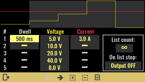
10.5. Programming output voltage using the list of values
The BB3 comes with simple “arbitary waveform generator” functionality that can be accomplished using the LIST commands. The following example changes in the loop output voltage between five output values each half a second long while current is set to 3 A.
|
INST CH1 |
Select the channel that has to be programmed. |
|
VOLT:MODE LIST |
Set voltage programming mode to the list of values. |
|
LIST:VOLT 5, 10, 20, 40, 0 |
Define sequence of output voltage. |
|
CURR:MODE LIST |
Set current programming mode to the list of values. |
|
LIST:CURR 3 |
Only one output current value is defined. Single value or number of values equivalent to other parameters (LIST:VOLT and LIST:DWEL) is allowed. |
|
LIST:DWEL 0.5 |
Only one value for the duration of each step is chosen. Single value or number of values equivalent to other parameters (LIST:VOLT and LIST:CURR) is allowed. |
|
LIST:COUN INF |
Repeat continuously LIST sequence. |
|
TRIG:SOUR IMM |
Define type of trigger. In this case the list execution will start immediately after INIT command is received. |
|
INIT |
Start the trigger. |
Resulting output voltage and current waveform is shown on the picture below.
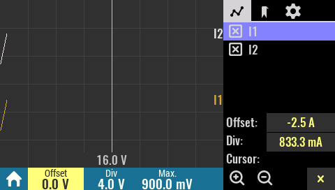
10.6. Create DLOG file
Data logging of multiple values can also be done using SCPI commands. The recorded values can be acquired from various BB3 resources (e.g. power channel output values, analog or digital inputs on MIO168 module, etc.), but can also be collected from other sources and programmatically added to a log file that can later be viewed on the device itself or transferred to EEZ Studio on a computer.
|
SENS:DLOG:CLE |
Resets all DLOG parameters (from previous session). |
|
SENS:DLOG:TRAC:REM "This is remark" |
Add DLOG comment. |
|
SENS:DLOG:TRAC:X:UNIT VOLT |
Set the X-axis units to Voltage. |
|
SENS:DLOG:TRAC:X:STEP 0.1 |
Set X-axis step (i.e. difference between two points) to 0.1. |
|
SENS:DLOG:TRAC:X:RANG:MIN 0 |
X-axis minimum value is set to 0. |
|
SENS:DLOG:TRAC:X:RANG:MAX 40 |
X-axis maximum value is set to 40 V (i.e. full range). |
|
SENS:DLOG:TRAC:X:LABel "U" |
X-axis label is set as “U” (as for voltage). |
|
SENS:DLOG:TRAC:Y1:UNIT AMPER |
Set the Y-axis units to Amperes for data set #1. |
|
SENS:DLOG:TRAC:Y1:RANG:MIN 0 |
Y-axis minimum value for data set #1 is set to 0. |
|
SENS:DLOG:TRAC:Y1:RANG:MAX 5 |
Y-axis maximum value for data set #1 is set to 5 A (i.e. full range). |
|
SENS:DLOG:TRAC:Y1:LABel "I1" |
Y-axis label for data set #1 is “I1” |
|
SENS:DLOG:TRAC:Y2:UNIT AMPER |
Set the Y-axis units to Amperes for data set #2. |
|
SENS:DLOG:TRAC:Y2:RANG:MIN 0 |
Y-axis minimum value for data set #2 is set to 0. |
|
SENS:DLOG:TRAC:Y2:RANG:MAX 5 |
Y-axis maximum value for data set #2 is set to 5 A (i.e. full range). |
|
SENS:DLOG:TRAC:Y2:LABel "I2" |
Y-axis label for data set #2 is “I2” |
|
INIT:DLOG:TRACE "/Recordings/test.dlog" |
Initate data logging into test.dlog file. |
|
SENS:DLOG:TRAC:DATA 1.1, 3.1 |
Add first data points. |
|
SENS:DLOG:TRAC:DATA 1.2, 3.2 |
|
|
SENS:DLOG:TRAC:DATA 1.3, 3.3 |
|
|
SENS:DLOG:TRAC:DATA 1.4, 3.4 |
|
|
SENS:DLOG:TRAC:DATA 1.5, 3.5 |
|
|
SENS:DLOG:TRAC:DATA 1.6, 3.6 |
|
|
SENS:DLOG:TRAC:DATA 1.7, 3.7 |
|
|
SENS:DLOG:TRAC:DATA 1.8, 3.8 |
|
|
SENS:DLOG:TRAC:DATA 1.9, 3.9 |
|
|
SENS:DLOG:TRAC:DATA 2.0, 4.0 |
Add last data points. |
|
ABOR:DLOG |
Close data logging session. |
Resulting data log that includes two recordings is shown on the picture below.
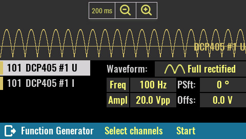
10.7. Generate a full-rectified signal with function generator
The DCP405 power module is fast enough to emulate a full rectified AC power source and thus can replace traditional AC mains transformer and bridge rectifier. The advantage is that the voltage and current can be changed in real time, which speeds up and simplifies testing.
|
INST CH1 |
Select the channel that has to be programmed. |
|
VOLT:MODE FUNC |
Change channel output voltage mode to function generator. |
|
VOLT:FUNC:SHAP FULL |
Select full-rectified waveform. |
|
VOLT:FUNC:FREQ 100 |
Set frequency to 100 Hz to emulate full-rectified 50 Hz power source (set frequency to 120 Hz if 60 Hz has to be emulated). |
|
VOLT:FUNC:PHAS 0 |
No phase shift is defined. |
|
VOLT:FUNC:AMPL 24 |
Output voltage amplitude is 24 Vpp. |
|
VOLT:FUNC:OFFS 0 |
Voltage output offset is set to zero. |
|
CURR:MODE FUNC |
Change channel output current mode to function generator. |
|
CURR:FUNC:SHAP DC |
Current waveform is DC. |
|
CURR:FUNC:AMPL 1 |
Current amplitude is 1 A. |
|
INIT:IMM |
Start function generator. |
Resulting output voltage and current waveform is shown on the picture below.