EEZ BB3 Enclosure & Bare Boards kit assembly instructions
Join the discussion on building a BB3 at EEVblog forum
Introduction
Instructions presented in this document are related to “BB3 Enclosure & Bare Boards” kit offered through a crowdfunding campaign.
This kit is not an end-user product. As such, it has not been subjected to any conformance testing, and it may not comply with some or any technical or legal requirement that are applicable to finished products including, without limitation, directives regarding electromagnetic compatibility and recycling for instance (WEEE, FCC, CE or UL). Assembling requires intermediate or advanced soldering skills and basic understanding of electronic circuits and computer programming skills.
If you need assistance, please contact us using contact form or join us on our Discord server (invitation) or post your problem on the EEVblog forum here. Or, feel free to open a New issue on GitHub here, but please check first to see whether a similar issue already exists).
The only tool required for the kit mechanical assembly is a medium Phillips head screwdriver. Of course, a multimeter for checking the wiring and voltage at a few points during assembly is recommended.
Kit assembly steps
1. Package content
The BB3 kit consists of the following parts, as shown in Fig. 1:
|
Item |
Description |
|
1 |
Pre-drilled enclosure top cover |
|
2 |
Pre-drilled enclosure bottom plate |
|
3 |
Enclosure front panel with mounted 4.3” TFT touch-screen color display |
|
4 |
Enclosure rear panel |
|
6 |
Plastic bag with wire harness and miscellaneous mounting parts |
|
10 |
Plastic bag with cooling fan and AC/DC converter mounting frame |
|
11 |
Set of 6 bare PCBs |
The part numbers in Fig. 1 (as well as on Fig. 2 and 3) are in line with those mentioned in the EEZ BB3 two channel kit assembly instructions, which contains the assembly instructions to be followed after the modules are soldered and tested. For this reason, certain numbers were skipped to preserve the unique marking.
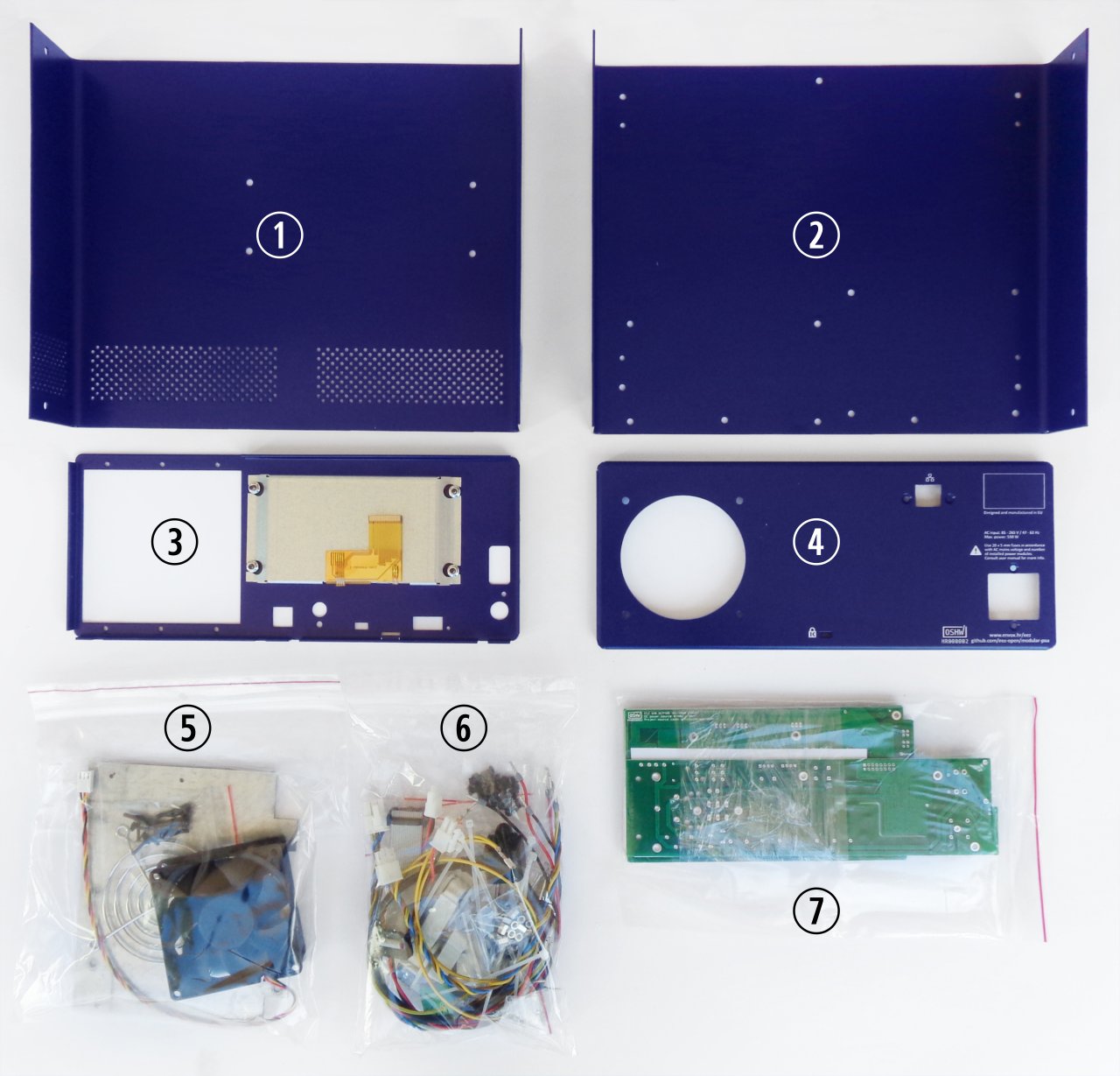
Fig. 1: “BB3 Enclosure & Bare Boards” kit content
2. Plastic bag contents
Please take some time to check that the contents of the plastic bags (item 5 and 6) include everything listed below.
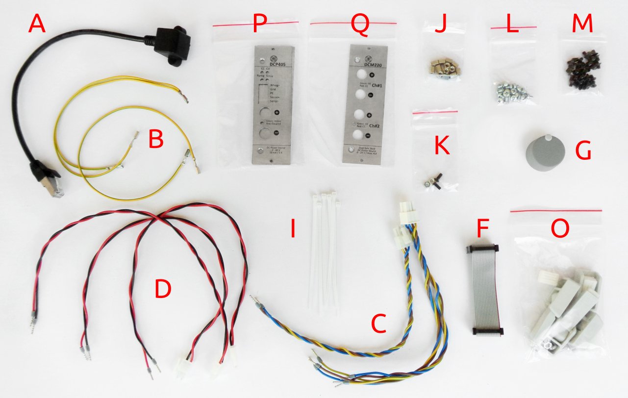
Fig. 2: Plastic bag content
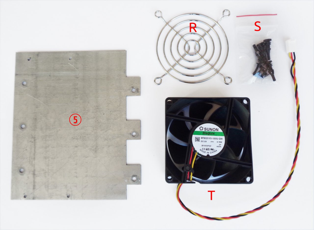
Fig. 3: Plastic bag content (cont.)
|
Item |
Description |
|
A |
Ethernet patch cable |
|
B |
Dual power module PE (Protective Earth) cable |
|
C |
Dual AC/DC power module AC input cable |
|
D |
Power module DC input cable |
|
F |
16-pin IDC flat cable |
|
G |
Encoder knob |
|
I |
Cable ties ×6 |
|
J |
Hexagonal M3×6 mm metal spacers ×13 |
|
K |
Mounting set for AC power inlet |
|
L |
M3×4 mm screws ×13 |
|
M |
M3×5 mm countersunk screws ×40 |
|
O |
Enclosure feet kit |
|
5 |
Mean Well AC/DC converter mounting frame |
|
P |
DCP405 module front panel ×2 |
|
Q |
DCM220 module front panel |
|
R |
Finger guard |
|
S |
Cooling fan mounting parts |
|
T |
12 VDC cooling fan |
3. PCB assembly
The BB3 kit comes with six printed circuit boards (PCBs). Both SMD and THT parts were used on the PCBs. The SMD parts have been selected to be easily installable using hand soldering, but will greatly benefit from the assistance of an illuminated magnifying glass. In general, a magnification of x8 should be more than appropriate. Almost all passive SMD components are 0805 size, but never smaller then 0603. Few ICs comes in very small packages (e.g. IC1, IC10 on the MCU module) so they will need extra care when soldering.
The same goes for buck controllers on power modules (IC1, IC2 on DCP405 and IC2, IC11 and IC13 on DCM220 module) since they have exposed thermal pads. For this reason, it will be simplest to solder them using a hot air soldering station. Since the PCB has a solder mask cut outs on the bottom side, it is also possible to apply the method shown in Dave’s video EEVblog #434.
IMPORTANT: Please pay special attention that thermal pads are well soldered because they are also functional GND. Lack of good contact can lead to permanent damage especially in the case of LT3763 controller on DCM220 module.
Required tools and accessories
- A soldering iron with a conical tip example1, example2
- A hot air soldering station example (more than ordinary skill with a soldering iron may make this optional)
- Solder wire (0.25 mm diameter example, and 0.7 mm example).
- Some solder wick / desoldering braid example
- Some solder flux. This is often used, via an applicator (resembling a syringe) or a very small brush. Example
- A magnifying glass with light example
- A pair of self-locking tweezers example
- A pair of sharp non-locking tweezers example1, example2
- Isopropyl alcohol example
- Heat transfer glue for fixing DCP405 pre-regulator heatsink example
- A PCB holder example
- Medium Phillips head screwdriver
The basic tool needed for measurements is an oscilloscope. But, if assembly is performed carefully so that there are no mistakes (e.g., the wrong part value, or the right part installed in the wrong place, or inadvertent solder fragment shorts between parts or PCB traces, etc.) a multimeter (DMM) will be enough to check basic functionality.
During testing and taking measurements, please note that a DCP405 power module channel’s negative output (OUT-) is NOT at ground potential with regard to the mains earth potential in the AC wiring. If you are using a multichannel oscilloscope which does not have isolated channels (the default!) you cannot simultaneously connect the test probe ground of one channel to a GND point and another channel to an OUT- point. This will interfere with normal operation of the current control loop because the current sense resistor will be bypassed.
The zip file below contains subfolders with module names. For each module there are schematics, BOM and parts placement picture. As example a parts placement picture for the MCU module is shown in the Fig. 4.
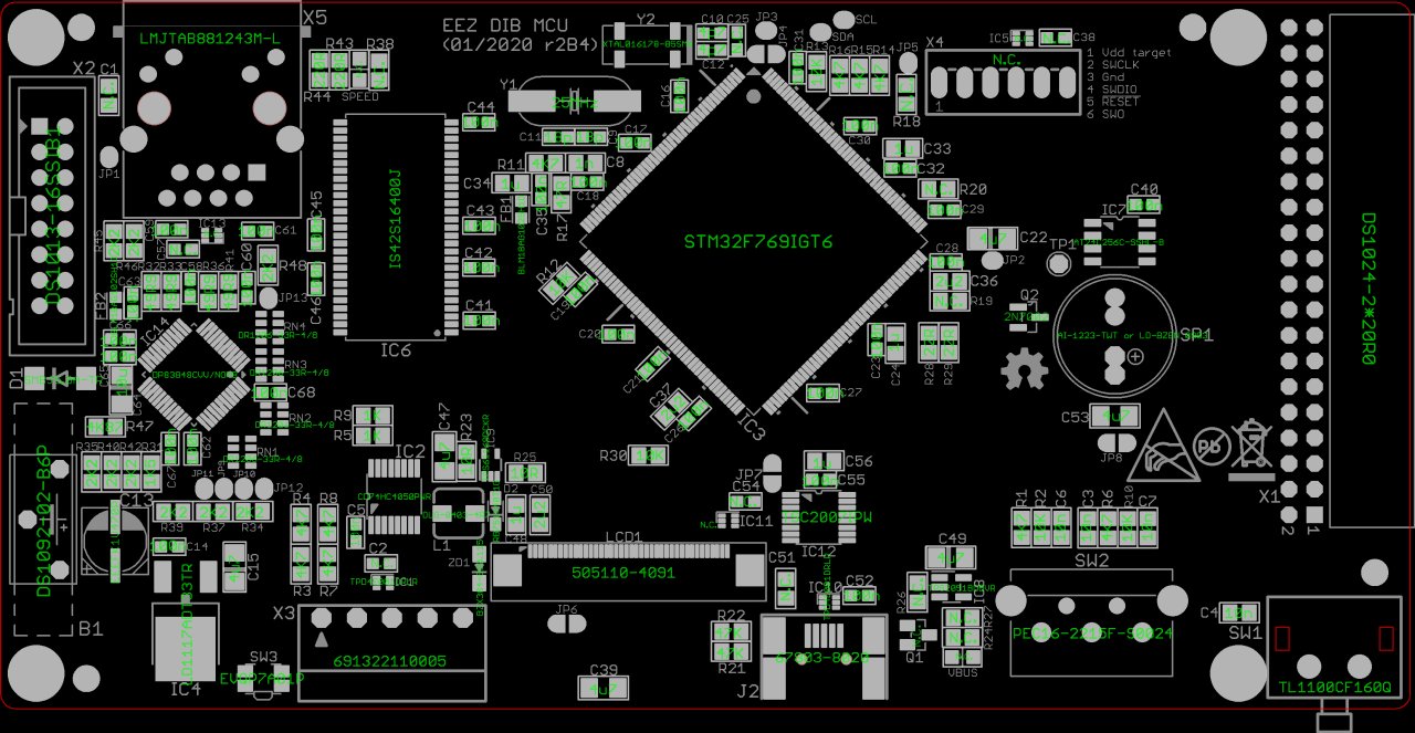
Fig. 4: Parts placement picture for the MCU module
All non-soldering parts are marked N.C. Furthermore, there are a number of jumpers on all PCBs. For normal functioning, you will not need to change any of the jumpers.
You can assemble the modules in the order you want. The BP3C backplane is the simplest so it can be a good place to start. In general, when assembling, the SMD parts should be mounted first and then the THT parts are followed.
The next module by complexity is the AUX-PS module. The two components on it require special attention. These are triacs (Q1, Q2) that should first be mounted on a heat sink (KK1) and then soldered (see Fig. 5).
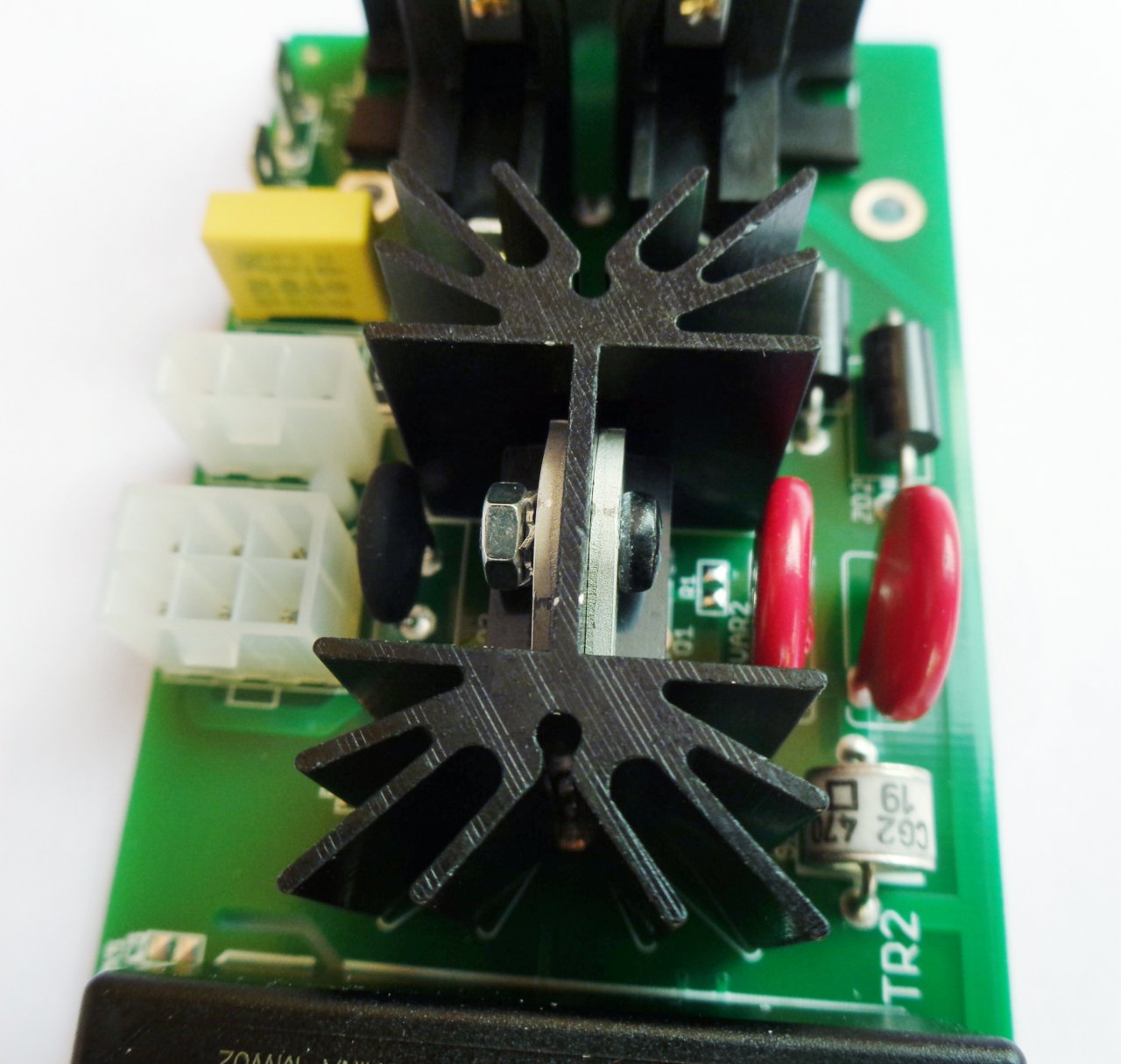
Fig. 5: Triacs mounted on heatsink
For the MCU module, besides the ICs (IC1, IC11) already mentioned in the small package there is nothing special to say. With the exception of the micro SD card socket (J1), all components are mounted on the top side of the PCB. The MCU (IC3) comes in a large package and should be mounted as usual for a package that has pins on all four sides: first solder one pin on opposite sides and then carefully proceed to solder all remaining pins. The same goes for IC14.
Do not insert the battery before the assembly of all modules is complete and ready for mounting in the BB3 enclosure.
Power modules have the largest number of components and will take the most time to assemble. Since there are two DCP405 PCBs it is possible to mount components simultaneously which can save some time. When assembling the DCP405 module, you can first complete the bias power supply section around the buck controller (IC2) and check that it outputs about 8-9 V (positive and negative rail). If that’s right you can complete that section by adding IC5 and IC6 which should give +5V and -5V at their outputs. You can now continue to fill the PCB with the rest of the components.
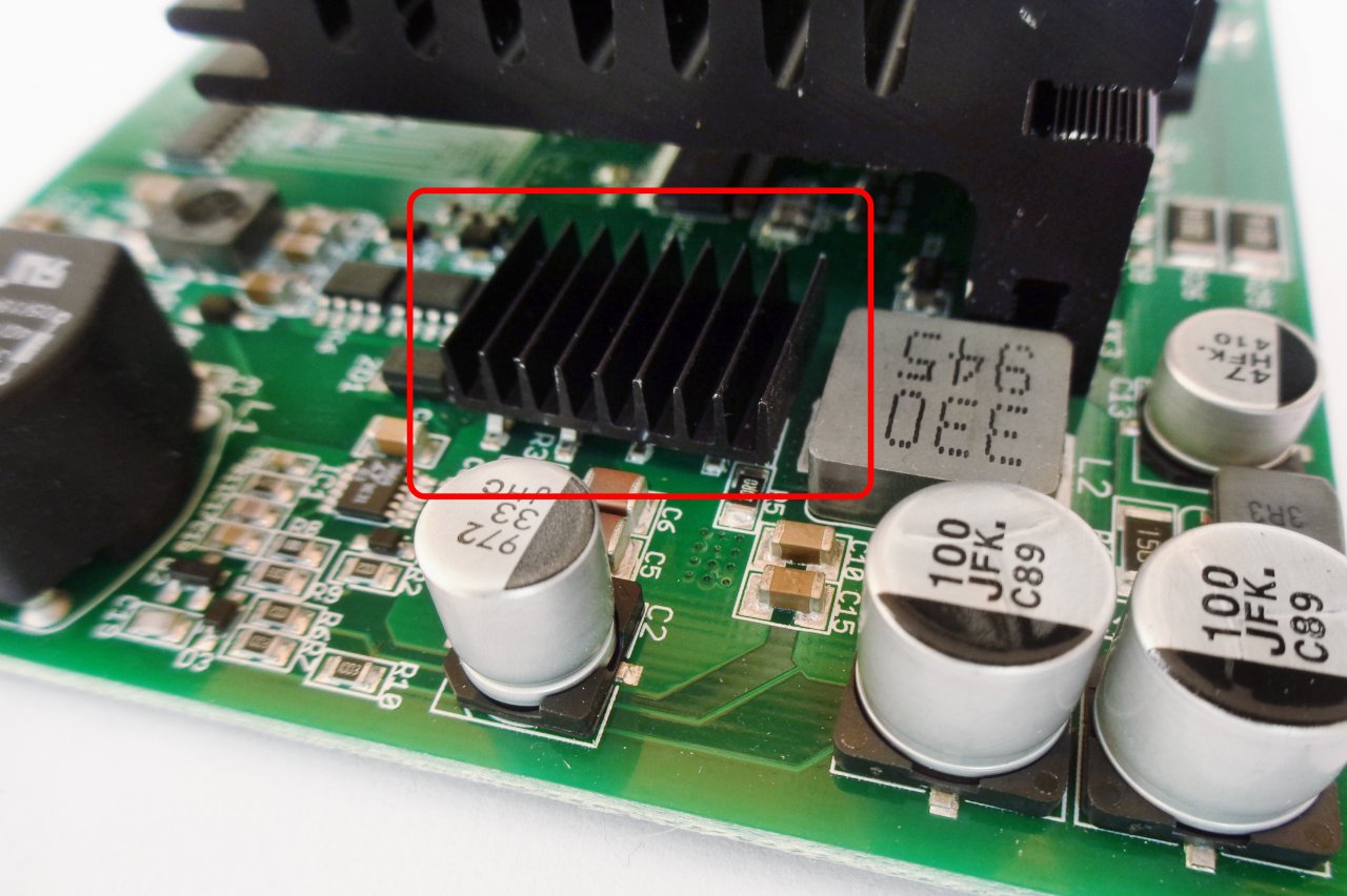
Fig. 6: DCP405 buck pre-regulator heatsink
The DCP405 requires the installation of two heatsinks. The larger heatsink serves to radiate heat from Q3, Q4 and Q5 and is fastened with M3x8 screws (not part of this kit). The smaller cooler will need to be pasted using heat transfer glue (listed under Required tools and accessories). However, the installation of the heatsinks can be done later if DCP405 module is not going to be tested with load that can draw more than 100 mA. When applying a glue for a small heatsink, allow it to dry for a few hours.
While the DCP405’s pre-regulator could easily withstand loads up to 3 A without heatsink, this is not the case with the post-regulator. Its Q3, Q4 transistors without being mounted on heatsink could instantly damaged at higher currents.
When assembling a DCM220 module, you can apply the same principle as in DCP405: first assemble the bias power supply (IC2), check that the outputs are about 7-8 V, add LDO (IC5), and if it gives +3.3 V, continue adding all other parts.
Before proceeding with mounting the power module in enclosure (see EEZ BB3 two channel kit assembly instructions), fix the front panels (item P and Q, Fig. 2). You will need six M3x5 screws (two per module, not part of this kit).
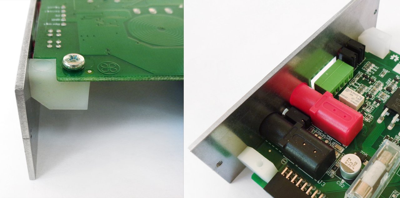
Fig. 7: Module front panel installed
Since in this kit the cooling fan does not come mounted on the rear panel you will need to do it yourself. This will require the contents of a item S and a finger guard (item R). First mount the four rubber holders as shown in Fig. 8.
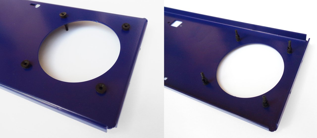
Fig. 8: Rear panel with fan holders
Then carefully attach the fan and finally mount the finger guard and secure it with four plastic fasteners (Fig. 9).
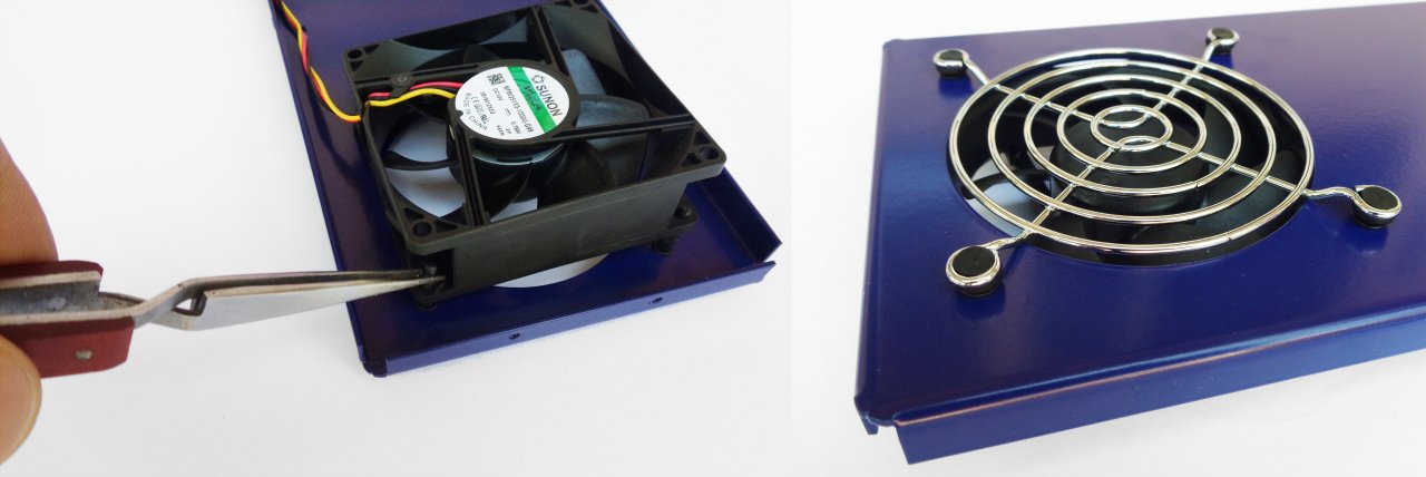
Fig. 9: Mounting fan and finger guard
4. Firmware downloading and module initialization
When all modules are assembled, we can proceed with their mounting into the BB3 enclosure. Before that, it will be necessary to put two fuses in the AC inlet (see recommendations in the User manual Section 2.8) and check that the AUX-PS outputs have +5 V and +12 V. If the required voltages are present, turn off the power and connect the MCU and AUX-PS module using a 16-pin IDC flat cable (item F, Fig. 2). Follow the procedure in the User manual Firmware upgrade section.
If the MCU module is correctly assembled, after downloading the firmware, assuming you have connected the display, a start page will appear on it and some errors may occur if, for example, you have not connected the cooling fan connector, or inserted a micro SD card or connected the BP3C backplane with the MCU module. Ignore these errors for a moment, turn off the power and continue assembly so you can insert power modules as well.
IMPORTANT: modules that are installed for the first time must be initialized. Therefore, you should not be surprised that even though you have put everything together correctly, the firmware will not recognize them at the next power up.
Initialization requires running the Module initialization script, which you can download here. You will need both .py and .res files. These files will need to be transferred to the micro SD card of the MCU module, the easiest way to do this is to use EEZ Studio. The procedure is the same as described in the User manual 13.2 Peripheral module firmware upgrade section with the destination folder being Scripts instead of Updates. Familiarize yourself with this procedure, as you will later need to download the firmware in the DCM220 after it has been initialized and successfully recognized by the master firmware.
After transferring both files, go to File manager and run the Module initialization script in the Scripts section. Fig. 10 shows the settings for initializing all three modules at once: two DCP405 on the first two slots and DCM220 on the third slot. When you have set the module parameters, select the Restart option.
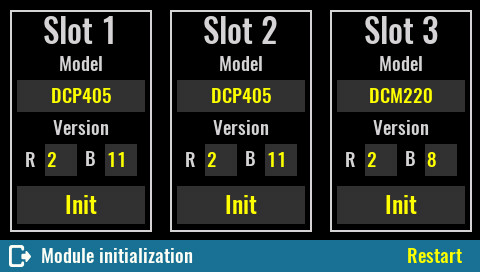
Fig. 10: Module initialization script
Power modules will also need to be calibrated. Follow the procedure in the User manual 12. Power modules calibration section.