9. System functions
Functions that are not related to a specific module or channel are called system functions and most are accessible from the status bar of the home page.
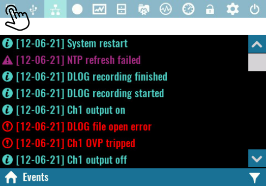
If SD card is not present or dysfunctional only the latest 50 events will be accessible via Event viewer. That events will not be written to non-volatile memory, and will be lost after the restart.
9.1.1. Events filtering
|
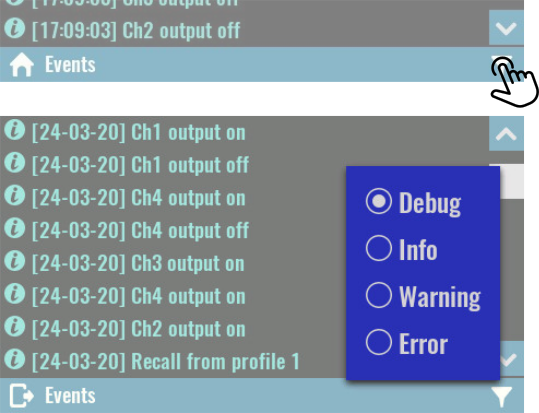
Four types of logged events exists and their appearance in the event viewer depends of the selected filter. The Debug filter represents the most comprehensive view that contains all type of events will Error filter allows appearance of error messages. |
|
|
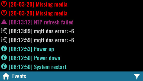
Events types identification is simplified by using different icons and colors. |
|
|
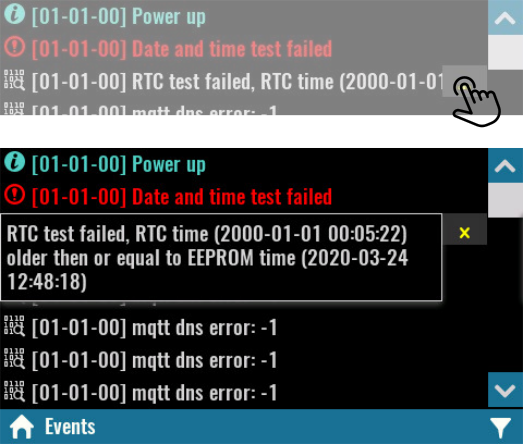
If the content of the message cannot be displayed in one line due to its size, an expansion option will appear. |
|
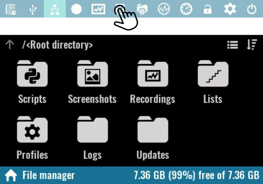
9.2. File managerFile manager lets you access and work with files on a SD card. The working data is organized into multiple folders (directories) as follows: |
|
- Lists – contains program lists that can be executed on the selected channel
- Profiles – location for user profiles
- Logs – recorded events that are accessible via Event viewer.
- Updates – contains firmware binary images that can will can be selected from module’s firmware download section.
|
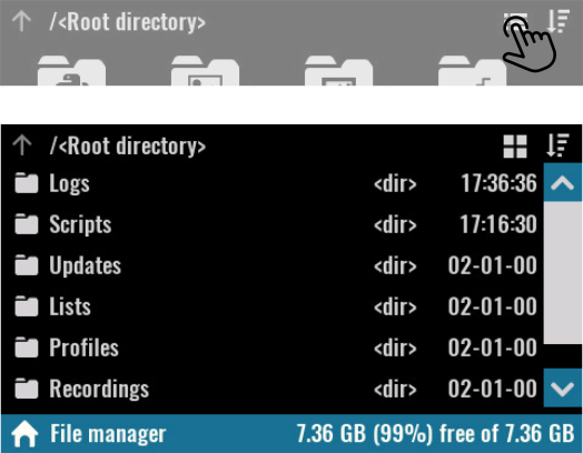
Folders and files in File manager can be displayed as list. |
|
|
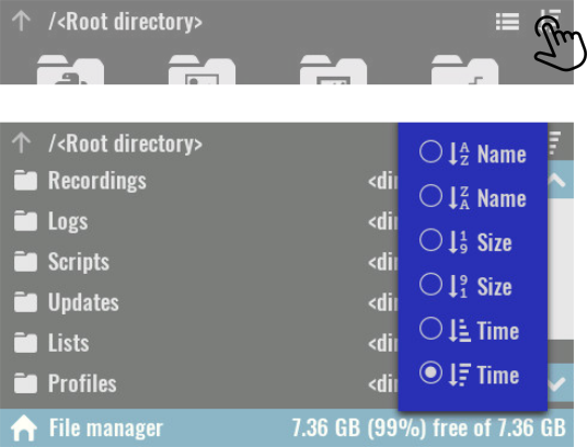
Files and folders displayed can be sorted by name, size and time in descending order and ascending order. Selecting the Sort icon will display a menu through which you can select the sorting method.
SCPI MMEMory:CATalog? MMEMory:CATalog:LENgth? MMEMory:INFOrmation? MMEMory:TIME? {<filename>}
|
|
|
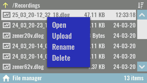
Clicking on a file name will open a menu whose options will be enabled or disabled depending on the file type and whether a computer connection is established.
Open Displays an image in .jpg format, or opens a viewer for logged data in .dlog format
Upload Initiates file transfer to the computer. If the file is large, the progress percentage will be displayed.
|
|
|
SCPI MMEMory:UPLoad? {<filename>}
Rename Rename a file or folder. SCPI MMEMory:MOVE {<source>}, {<destination>}
Delete Deleting a file or folder.
SCPI MMEMory:DELete {<filename>} |
|
9.3. User profiles
|
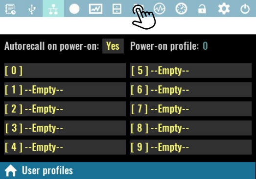
User profiles are used to store and recall system parameters and parameters of installed modules. There are 10 profiles available that are displayed by number and name.
The profile 0 has a special status, i.e. it contains the current parameter states. Its name cannot be defined, but when a recall is made from a profile, it will receive its name.
SCPI MEMory:STATe:CATalog? |
|
Autorecall on power-on
Defines whether or not to load parameter states from the selected user profile at power up.
When selected, a Power-on profile number is also displayed, that is set by default to user profile 0.
If this option is off, the power up parameters will be set to initial values (i.e. “factory settings”).
Parameters stored in an empty user profile cannot be selected as an auto-recall profile.
SCPI
MEMory:STATe:RECall:AUTO ON
|
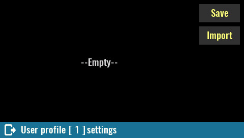
Save Saving the parameter state can be done in an empty user profile or one that has already been used. The following system states and parameters will be stored in non-volatile memory at the position of the selected user profile:
|
|
- Output set voltage, voltage limit, and voltage step
- OVP status, and OVP delay
- Output set current, current limit, and current step
- OCP status and OCP delay
- Output power limit, OPP level, OPP status and OPP delay
- OTP level, OTP status and OTP delay
- Power on state
SCPI
*SAV {<profile>}
|
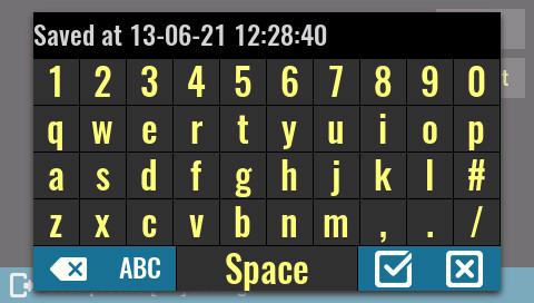
When saving a user profile, it is necessary to define its name (i.e. Remark as shown on next picture). In case of saving to an empty user profile, the name will be offered as a combination of Saved at and the current date and time. If saved to previously used profiles, an existing name will be offered.
SCPI MEMory:STATe:NAME {<profile>}, {<name>} |
|
|
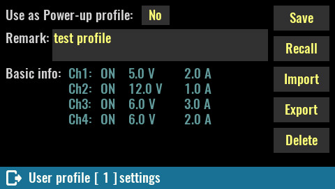
Use as Power-up profile Specifies whether the initial states will be loaded or not from the profile if the Autorecall on power-on option is selected.
SCPI MEMory:STATe:RECall:SELect {<profile>}
Recall Use this option to load immediately the parameter status from user profile. |
|
SCPI
*RCL {<profile>}
Delete
Empty user profile and reset its name (remark) to –Empty–.
SCPI
MEMory:STATe:DELete {<profile>}
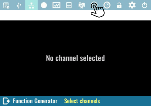
9.4. Function generator
A simple built-in function generator makes it easy to define some common waveforms on sourcing channels such as DCP and DCM power modules or analog outputs on SMX and MIO modules. It can also be used to define patterns on the digital outputs of the MIO module.
IMPORTANT: since the function generator dynamically changes the voltage and current, make sure that they are within the limits that the connected load can withstand. If it is a sensitive load, it is recommended to set voltage and current limits (see Channel protections section) because the function generator will take them into account (together with set max. power) while it is active.
See also the Hardware OVP section to find out how it can affect this function.
|
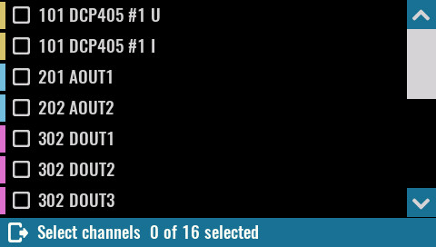
When open the Function generator choose the Select channels option to display a list of all resources supported in the current firmware version will appear.
|
|
|
In the example in the picture on the right, these are the DCP (current and voltage) two analog outputs on the SMX and the digital and analog outputs of the MIO module.
|
|
|
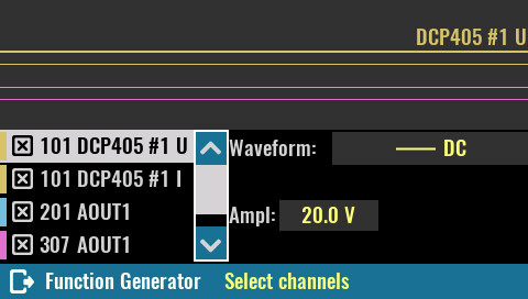
Upon confirmation, the selected resources will appear in the list of the main configuration page of the function generator.
Using checkboxes, you can choose which resources will be displayed, which can give a clearer view if more resources with e.g. significantly different frequencies are selected.
|
|
|
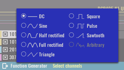
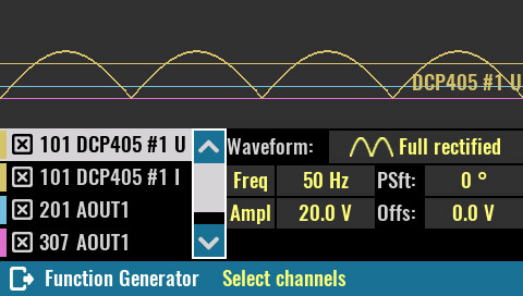
Waveform: The waveform shape can be selected separately for each of the selected resources from the list of currently supported shapes:
|
|
- Half rectified – useful for simulating a discrete power rectifier with the difference that both its voltage and current can be controlled. Positive half of the AC wave is passed, while the negative half is blocked. Adding DC offset is also possible if needed.
- Full rectified – similar to half rectification but both half of the AC wave is passed with positive polarity (it corresponds to the absolute value function in mathematics).
- Triangle – symmetrical triangular signal
- Square – a rectangular signal that has a duty cycle fixed at 50%.
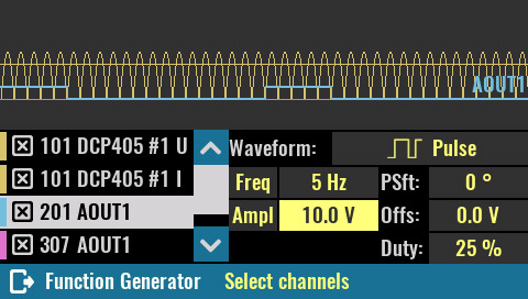
- Pulse – a rectangular signal with variable duty cycle (default is 25%).
- Sawtooth – asymmetrical triangular signal with gradual rising edge and steep falling edge
Important notice: don’t expect that a combination of say two half rectified signals shifted 180 degrees in phase will result in a bipolar (AC) signal. This is not possible with single quadrant DC sources such as DCP or DCM no matter how you connect their outputs (at best you can get a full rectified signal, at worst damage to one or both power channels).
Due to the technical limitations on the modules as well as the way the signal is generated, signal distortions as well as jitter can be expected. The final appearance of the generated signal should therefore be checked on an oscilloscope. Also note that generating signals on power channels can generate audible sound.
SCPI
[SOURce[<n>]]:VOLTage:FUNCtion:SHAPe {DC|SINe|HALFrectified|FULLrectified|TRIangle|SQUare|PULSe|SAWTooth}
[SOURce[<n>]]:CURRent:FUNCtion:SHAPe {DC|SINe|HALFrectified|FULLrectified|TRIangle|SQUare|PULSe|SAWTooth}
SOURce:FUNCtion:SHAPe {DC|SINe|HALFrectified|FULLrectified|TRIangle|SQUare|PULSe|SAWTooth}
SOURce:DIGital[:OUTPut]:FUNCtion:SHAPe {pin}, {SQUare|PULSe}
|
Depending on the selected waveform shape, it will be possible to set one or more of the following parameters:
|
|
- Offs / Max – the offset can be set when Ampl is selected and determines the DC level of the signal center. For example, if the amplitude of the voltage sinusoidal signal on the DCP channel is 20 V, in order to generate a complete period it will be necessary to set the offset to 10 V or more. For a smaller offset the lower half of the signal period will be zero, i.e. it will completely disappear if the offset is set to 0. Also on the other side if the offset increases above 30 V the positive half will start to be set to max. value (40 V) until it completely disappears at an offset of 40 V. The Max can be used in combination with the Min option. It specifies the maximum value of the generated signal.
- Psft – phase shift (0 – 360 degrees) of the signal that is repeated periodically (all except DC).
- Duty / PWdt – Duty cycle of the pulse waveform when the frequency is set (0 to 100%) or pulse width when the period is set.
- Mode – choice of generating Voltage or Current (MIO module AOUT1 and AOUT2 only).
|
When more than one periodic signal is defined, the display will adapt to the signal with the lowest frequency so that two of its periods are displayed. |
|
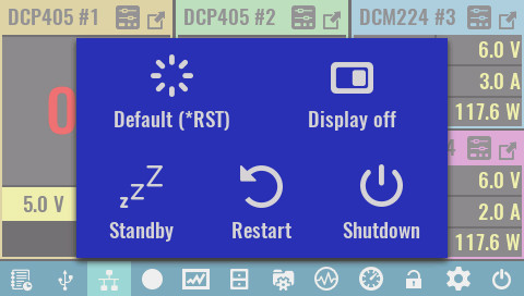
Standby mode keeps the MCU module powered that is indicated with the Standby indicator on the front panel. The power up can be initiated by tap and hold action anywhere on the screen.
SCPI
SYSTem:POWer OFF
Restart
This action is equivalent to recycling input power. On power up all modules will be initialized, self test will be performed and initial values will be set depending on the selected user profile and Autorecall on power-on status as defined in User profiles.
SCPI
SYSTem:RESet
Shutdown
Initiates a graceful shutdown that ensures that the latest information are stored in non-volatile memory. Wait until a message appears on the screen that EEZ BB3 can be safely turned off.
Display off
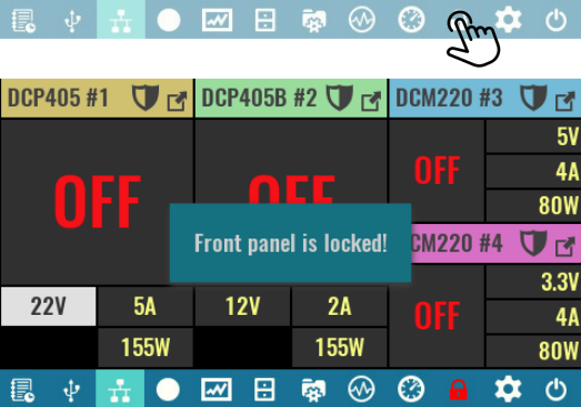
While the display is off, future user interaction will be disabled until it is turned on again. Turn the display back on by tap and hold action anywhere on the screen.
SCPI
DISPlay OFF
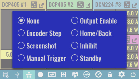
Encoder Step
Cycle through the sensitivity of the encoder to change the selected output value (voltage, current or power). Initially, the encoder is set to Auto mode when the change will depend on the speed at which it will rotate. Its turn sensitivity in one direction or the other can be changed in the Encoder settings.
Screenshot
Take screenshots of current screen content and save to SD card in the screenshots folder. The image will be saved in jpeg format and its name formatted as yyyy_mm_dd-hh_mm_ss.jpg
Taking a screenshot is not possible while DLOG recording is in progress.
Manual Trigger
Allows the user switch to be used to initiate the trigger system (see General trigger settings).
Output Enable
When two or more channels are in tracking mode, this option allows their outputs to be switched on and off simultaneously
Home/Back
When this option is selected, user switch can be used as an option to return to the previous or main page. It can also be used to exit maximized channel view.
|
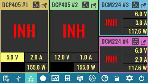
Inhibit This option is selected by default, when user switch can be used to enter inhibit mode when all active outputs will be temporarily disabled that is indicated with INH text. To exit inhibit mode, you will need to press the button once again.
|
|
Standby
If EEZ BB3 is turned on and this option is selected, the first time a button is pressed, it goes into standby mode. The next time the button is pressed, it exits standby mode.