4. Unpacking and Checking the EEZ BB3
To remove the EEZ BB3 from its packaging and check the equipment for completeness, proceed as follows:
- Check the package for damage
- Carefully unpack the EEZ BB3 and the accessories
- Check the package contents for completeness using the Delivery list and package contents
- Check the equipment for any visible shipping-related damage or other mechanical problems, e.g. loose parts inside
If there is damage or anything missing, contact the supplier and the carrier who delivered the EEZ BB3. Do not operate the EEZ BB3 in this case.
Retain the original packing material. If the EEZ BB3 needs to be transported or shipped later, you can use the material to protect the exposed and fragile elements on the front panel.
The EEZ BB3 must be stored in dry, closed, indoor premises. If the EEZ BB3 was transported under extreme temperatures, it is recommended that you allow a minimum of two hours to reach the appropriate temperature before operating the EEZ BB3.
4.1. Delivery List
4.1.1. Assembled unit
The EEZ BB3 comes with the following components:
- EEZ BB3 preloaded with selected peripheral modules
- AC mains cable for the selected region
- Thank you leaflet with links to online documentation
- Set of DC power cables, clip-on probes and crocodile clips (optional)
4.1.2. Kit version (crowdfunding version)
The EEZ BB3 kit is not an end user product. As such it was not put into any conformance testing and it may not comply with some or any technical or legal requirement that are applicable to finished products including, without limitation, directives regarding electromagnetic compatibility, FCC, CE, or UL.
Assembling and using the EEZ BB3 requires an understanding of electronic circuits. Additionally, basic computer knowledge is recommended for performing firmware upgrades.
The EEZ BB3 comes in different kit versions. Typical content of the kit version:
- Enclosure kit
- Wire harness, nuts&bolts package
- Set of basic modules (i.e. AUX-PS, MCU and BP3C)
- Set of selected peripheral modules
- Read me first leaflet with links to online documentation
- Set of DC power cables, clip-on probes and crocodile clips (optional)
Kit assembly instructions are available on the following link: https://bit.ly/2VtWsZu
4.2. Placing the EEZ BB3
If the EEZ BB3 is operated on a bench top, the surface must be flat. You can place the EEZ BB3 horizontally, or in a slope position by unfolding the front feet.
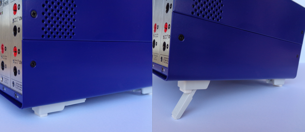
Fig. 1: Adjustable front feet
The feet can fold in if they are not folded out completely or if the EEZ BB3 is shifted. Collapsing feet can cause injury or damage the EEZ BB3.
- Fold the feet completely in or out to ensure stability of the EEZ BB3.
- Never shift the EEZ BB3 when the feet are folded out.
- When the feet are folded out, do not work under the EEZ BB3 and avoid placing anything underneath.
The front feet in folded out position can break if they are overloaded. The overall load on the folded out feet must not exceed 50 N. If the front feet are folded in, it is possible to stack the EEZ BB3 with more instruments securely.
4.3. Starting the EEZ BB3
The EEZ BB3 is equipped with an AC power supply connector, (IEC C14 type) which can be used with different AC power voltages in wide range without need to adjust manually input voltage or frequency.
IMPORTANT: The EEZ BB3 must only be connected to an outlet that has a functional ground contact
- Check the AC line voltage.
- Check the fuse type and if necessary replace the fuse type suitable for the line voltage.
- Connect the EEZ BB3 to the AC mains using the supplied power cable.
4.4. Replacing the fuses
The EEZ BB3 has main power fuses, which are located on the rear panel of the unit. Handling the fuses while power is on can lead to electric shock. Therefore, before opening the fuse holder (see Fig. 2), make sure that the EEZ BB3 is disconnected from AC power.
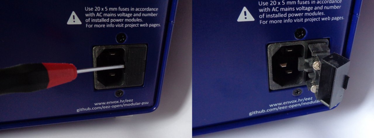
Fig. 2: Opening the fuse holder
To replace the fuses the EEZ BB3 has an externally accessible fuse holder combined with the IEC socket.
The nominal current of the fuse depends on the line voltage and number of installed power modules. Select the fuses according to the voltage of the AC line, as specified in Table 1. Fuse size is 20 x 5 mm of time-lag type and has to be rated for the selected AC line voltage.
|
No. of power modules |
1 |
2 |
3 |
|
115 V |
2 x 3.15 A |
2 x 6 A |
2 x 8 A |
|
230 V |
2 x 2 A |
2 x 4 A |
2 x 6 A |
Table 1: Fuses selection
4.5. Battery replacement
The CR2032 coin cell battery is used as a power backup for the RTC. It uses a non-rechargeable lithium battery that will need to be replaced when its voltage drops to approximately 90 % of its rated value. The current battery value can be viewed on the System information page.
To access the EEZ BB3 interior, First, turn off the EEZ BB3 and unplug the power cord from the back, then remove the top cover, which is secured by four screws (two on each side).
Fig. 3 shows where the battery is located. You can remove the existing battery by pinching it. When inserting a new one, keep in mind the polarity (+ side must face inwards).
Do not use metal pliers instead of your fingers to insert or remove the battery as it may cause a short circuit. If you cannot reach the battery with your fingers, use a plastic tweezers instead.
Do not expose the battery to high temperature or fire. Keep it out of the reach of children. Improper change of a battery may cause damage, fire or explosion.
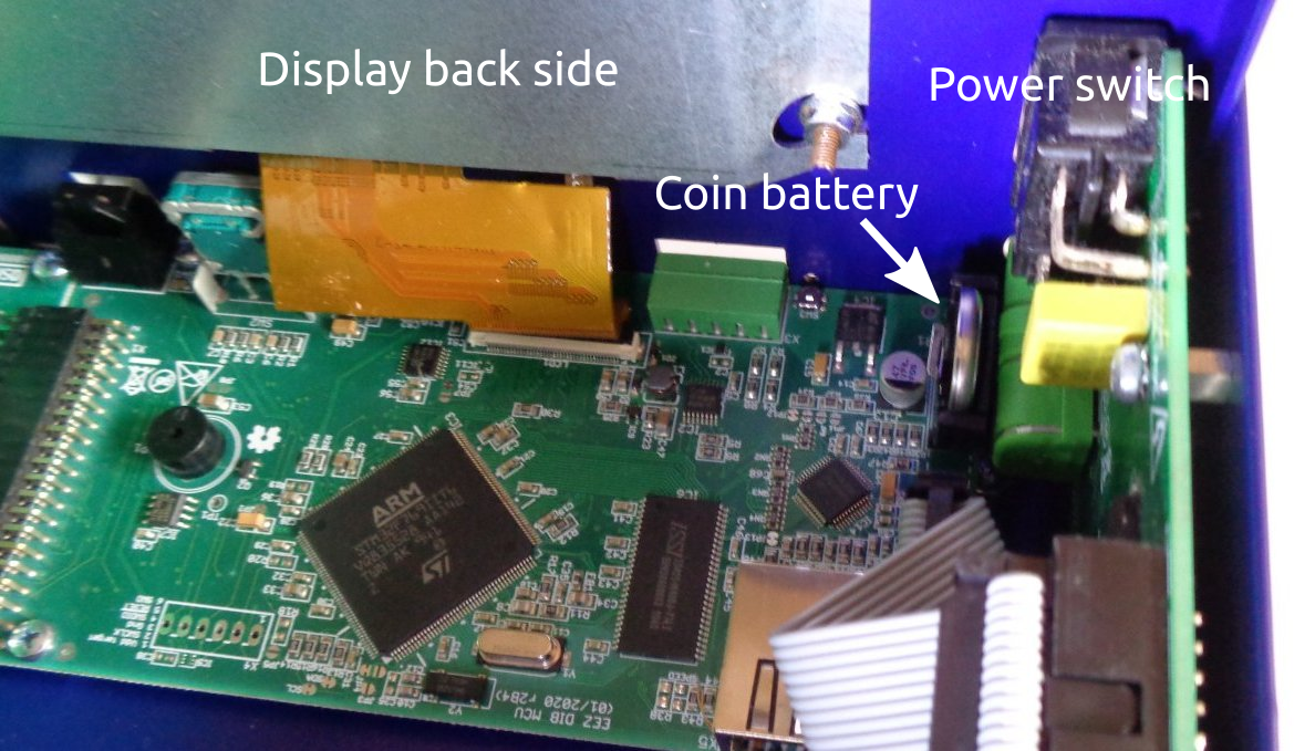
Fig. 3: Coin battery location (MCU r2B4)
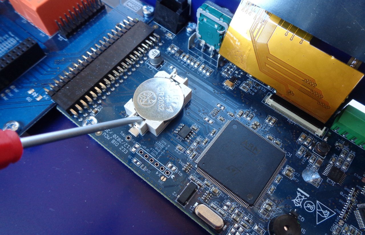
Fig. 4: Coin battery location (MCU r3B3)
4.6. Micro SD card (non-volatile memory)
The EEZ BB3 uses a micro SD card as a non-volatile memory. Due to its small size, extra care will be required when inserting and pulling out to prevent damage to the card or socket.
Attention should also be paid that the card is inserted correctly into the socket otherwise it could fall inside the enclosure. Therefore, it is recommended that the EEZ BB3 be completely switched off (not in standby mode!) when the card is inserted.
Fig. 5 shows how the card should be positioned when inserted: its connectors should be facing up (i.e. must be visible).
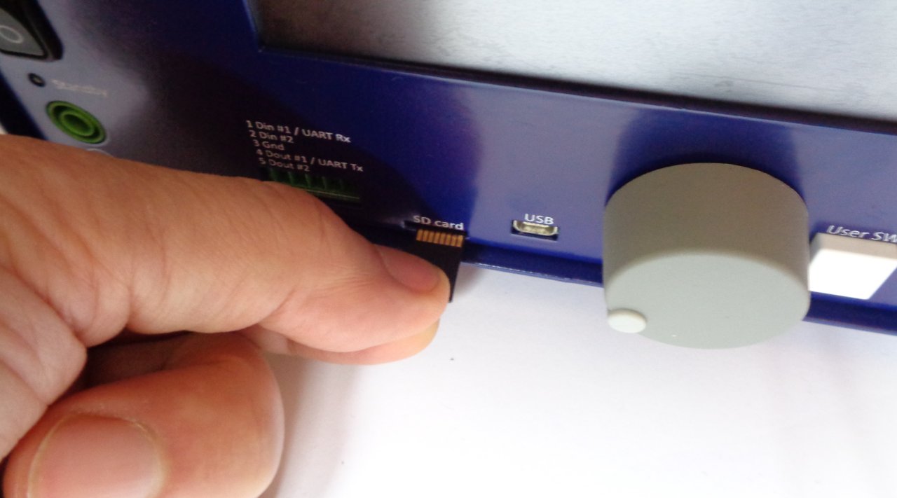
Fig. 5: Micro SD card insertion