10. Channel protections
Power modules are designed with multiple protection functions to avoid various unexpected conditions, for example output values exceeding the set limits which (if unchecked) could cause permanent damage to a connected device or the power module itself.
|
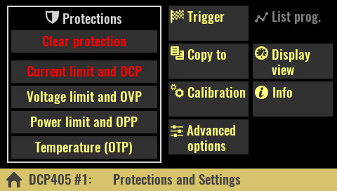
Clearing an activated protection mode, disabling protection modes or setting protection mode parameters may be accessed via Protections section on the Channel protection and settings page.
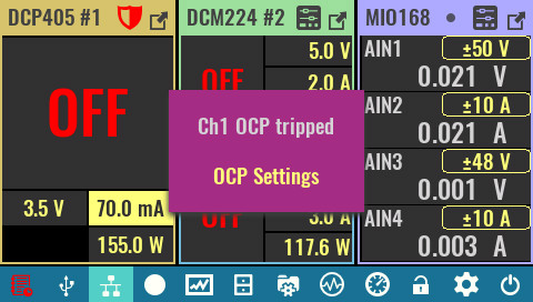
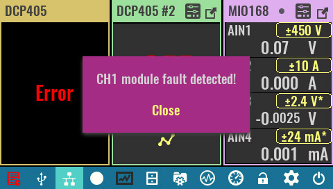
If any of enabled protections tripped, as for example over-current protection, popup message will appear and channel settings icon will be changed to shield icon colored in red.
|
|
|
Clear protection Use this option on Protections and Settings page to clear all tripped protections so that channel outputs can be re-enabled as needed. The status of active protections is not affected by this option. |
|
|
The same option could be used from tripped protection settings page to clear related protection trip. |
|
|
SCPI OUTPut:PROTection:CLEar CURRent:PROTection:STATe OFF POWer:PROTection:STATe OFF VOLTage:PROTection:STATe OFF SYSTem:TEMPerature:PROTection:STATe OFF, <sensor> |
|
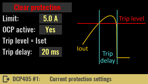
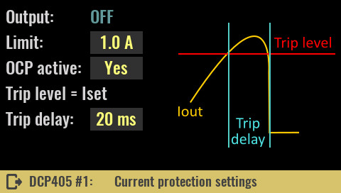
10.1. Current limit and OCPLimit Defines the max. value of the output current that the user will be able to set. The initial value is max. current the module can source (e.g. 5 A for the DCP405 module).
|
|
|
Changing the limit will also affect graphical views (vertical bar, horizontal bar and YT views), if the display settings of the channel is set to Limit (see Display view page). For example, if the limit is set to 1 A, this value will become 100% of the scale instead of only 20% when the limit is at 5 A.
SCPI CURRent:LIMit {<current>}
OCP active The OCP (Over-Current Protection) feature is software protection that will activate when drawn current reaches the set value of the allowed output current. This is a software version of what is known as e-fuse or electronic fuse. A protection mode trip will be recorded in the event log and the channel output will be turned off.
Use this option to turn OCP on or off. If OCP is off, if the output current reaches the set value (Iset) the channel will switch from CV to CC mode without turning off the channel output.
SCPI CURRent:PROTection:STATe {<bool>}
Trip delay If the OCP is enabled and the output current reaches the set value (Iset), an OCP trip will occur at the earliest after the set delay time expires.
SCPI CURRent:PROTection:DELay {<time>} |
|
10.2. Voltage limit and OVPLimit Defines the max. value of the output voltage that the user will be able to set. The initial value is max. voltage the module can source (e.g. 40 V for the DCP405 module).
SCPI VOLTage:LIMit {<voltage>}
OVP active |
|
|
The OVP (Over-Voltage Protection) is software protection that will activate when output voltage reaches the programmed value. Protection trip will be recorded in the event log and the channel output will be turned off.
Turns OVP on or off. If OVP is off (which is default), when the output voltage reaches the set value (Uset) the channel will enter the CV mode (which is normal behavior if the connected load does not draw more current than the maximum set). Therefore, when activating OVP without load or with connected load that draws less than the set current, the channel will enter CV mode and the OVP will immediately trip. To avoid this the channel should be in CC mode prior to the output being turned on.
SCPI VOLTage:PROTection:STATe {<bool>}
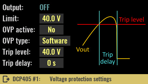
OVP type Selection between software (SW) and hardware (HW) OVP is only possible with DCP405 modules.
SCPI VOLTage:PROTection:TYPE SW
Trip level The trip level value may be greater than or equal to the set voltage (Uset) and determines the value of the output voltage at which the OVP will trip. In case the set value of the output voltage increases, the trip level will automatically increase. For example, if the trip level was set at 10 V while the output voltage was also at 10 V and its value increased to 12 V, the trip level value would also increase to 12 V. But, if the voltage drops to say 5 V, the trip level will remain unchanged.
Max. trip value is 0.5 V greater than max. output voltage (40.5 V for DCP405, 20.5 V for DCM220 or 24.5 V for DCM224 module).
SCPI VOLTage:PROTection {<voltage>}
Trip delay If the OVP is enabled and the output voltage reaches the set trip level, an OVP trip will occur at the earliest after the set delay time expires.
SCPI VOLTage:PROTection:DELay {<time>} |
|
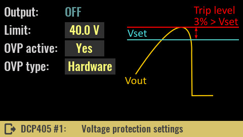
Please note that there are situations where the HW OVP can trip even though everything is fine with the DCP405 module. This is the case of “down” programming, i.e. quickly setting the voltage from higher to lower values. To understand why this could happen one needs to know the working principle of HW OVP. At the heart of this protection is a fast comparator that compares the set (U_SET) and measured output voltage (U_MON). If the U_MON is greater than about 3% of U_SET the comparator will activate a crowbar that will short-circuit the output and the channel will turn off.
At the initial voltage setting (from zero to U_SET value) U_MON has no reason to be greater than U_SET at any point unless we have some abnormal situation, e.g. unusually large overshoot (DCP405 is faulty) or let’s say a significantly higher input voltage is connected: let’s say a 12 V battery, and U_SET is set to a significantly lower value of 3 V.
However, in case the output voltage is higher than zero, say 20 V and we want to lower it to 10 V, in the case of an ideal DC source this would happen instantaneously and U_MON could not be higher than U_SET at any time. Since the DCP405 is not ideal, although it can lower the voltage very quickly thanks to the down-programmer circuit and even though it has a small Cout, it can still happen that the down-programmer fails to discharge the Cout fast enough, so reducing U_MON will delay setting a new (lower) U_SET. If this difference happens to exceed 3% the HW OVP will trip. The chance of this happening is higher the higher the Cin of the device that the DCP405 powers.
For the above reason, you may need to turn off the HW OVP or activate the SW OVP when using program lists or function generators.
Important note: The DCP405 power module can be used to charge batteries. In this case, never connect the battery to the output terminals while output is disabled and HW OVP is enabled! As soon as the output is enabled, it will certainly lead to the HW OVP tripping, which in case the battery is insufficiently discharged, can result in drawing currents of the order of several tens of amperes.
Firmware 1.7.4 solves this problem when the Prohibit output enable if external voltage detected option is enabled (see System protection page).
|
The third OVP control is software based and will emulate HW OVP in case none of the two protections described above are active. In this case, any measured voltage (U_MON) greater than approx. 3% of the set (U_SET) will turn off the power output and set the module to error mode. This is the final over-voltage protection that should turn off the output of the DCP405 module in case the previous two were not active. |
|
|
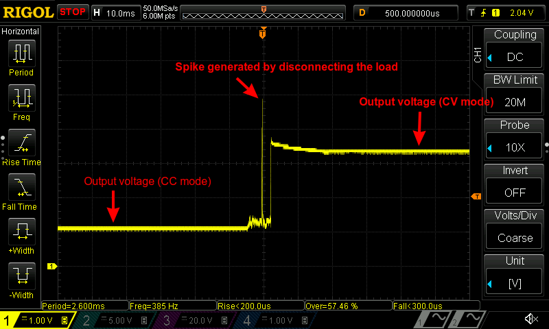
Note that there is a possibility for a “false positive” situation here. One example is when the output was in CC mode, then the output voltages (U_MON) will be less than the set voltage (U_SET). If the load is suddenly disconnected due to connecting wire inductance, a spike may be generated that may exceed the set voltage value (U_SET). The module will go into error mode even though everything is fine with it. This is a warning that such a practice should be avoided, and that the output enable/disable option should be used. |
|
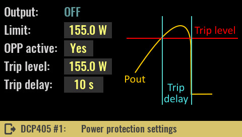
10.4. Power limit and OPPLimit Defines the max. value of the output power that the user will be able to set. The initial value is max. power the module can source (e.g. 155 W for the DCP405 module).
SCPI POWer:LIMit {<power>}
OPP active |
|
|
The OPP (Over-Power Protection) is software protection that will activate when output power reaches the programmed value. Protection trip will be recorded in the event log and the channel output will be turned off.
SCPI POWer:PROTection:STATe {<bool>}
Trip level The trip level value may be less than or equal to the set limit and determines the value of the output power at which the OPP will trip. When the power limit is set to a lower value, the trip level will also decrease.
SCPI POWer:PROTection {<power>}
Trip delay If the OPP is enabled and the output power reaches the set trip level, an OPP trip will occur at the earliest after the set delay time expires.
SCPI POWer:PROTection:DELay {<time>} |
|
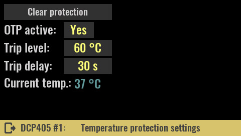
10.5. Temperature (OTP)OTP active The OTP (Over-Temperature Protection) is software protection that will activate when the temperature measured on the channel’s temperature sensor is equal to or greater than the set trip level value for a duration of trip delay.
Protection trip will be recorded in the event log and the channel output will be turned off.
|
|
|
Dual channel modules like the DCM220 or DCM224 have two temperature sensors, one for each channel.
SCPI SYSTem:TEMPerature:PROTection:STATe {<bool>} [, <sensor>]
Trip level The trip level value may be less than or equal to the set limit and determines the value of the measured temperature at which the OTP will trip.
SCPI SYSTem:TEMPerature:PROTection {<temperature>}, <sensor>]
Trip delay If the OTP is enabled and the temperature reaches the set trip level, an OTP trip will occur at the earliest after the set delay time expires.
SCPI SYSTem:TEMPerature:PROTection:DELay {<delay>}, <sensor>
|
|