7. Basic operations
7.1. Turn channel output on and off
|
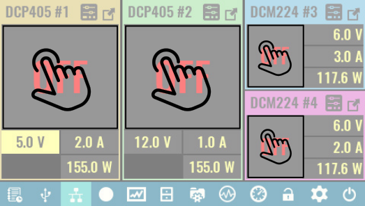
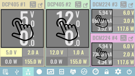
Turn channel on (OE on)
Turning the channel output on is performed by taping anywhere inside the main channel display area. The changed output state is indicated by display of the measured output values instead of “OFF”.
SCPI OUTPut ON OUTPut ON, <channel> |
|
|
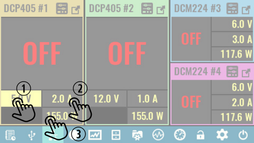
Turn channel off (OE off)
Turning the channel output off is performed by taping anywhere inside the main channel display area. The content of that area will be replaced with “OFF”.
SCPI OUTPut OFF OUTPut OFF, <channel> |
|
7.2. Set channel output values
Channel output values can be set regardless of the currently selected display view and channel output state as long as a trigger mode is not active (i.e. channel’s trigger is set to Fixed).
By default clicking the encoder switch navigates between editable parameters; when a parameter is highlighted (as shown in the figure below) its value can then be set with the encoder knob.
|
1 |
Set output voltage
Tap inside the voltage area of the channel secondary display area. If it is already selected (as shown), a keypad will appear as described in Data input methods. The voltage set here is the max. output voltage when channel is in CV mode.
SCPI VOLTage <voltage> |
|
|
2 |
Set output current
First tap the current area of the secondary channel display. A second tap is required if this option was not selected previously (as in the above example). The current set here is the max. output current when channel is in constant current (CC) mode.
SCPI CURRent <current> |
|
3 |
Set output power limit
Follow the above described procedure.
Note that when a power output limit is specified, it is the product of the voltage and current parameters used to calculate the output power limit rather than the actual measured output values. For example, if power limit is set to 100 W (DCP405) then set current cannot exceed 2.5 A for a max. voltage of 40 V. Similarly the output voltage cannot be set above 20 V if max. current is selected as 5 A even if the actual measured output current with a connected load is well below the set limit.
SCPI POWer:LIMit <power> |
7.3. Data input methods
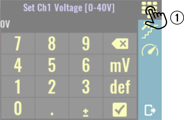
In addition to the physical rotary encoder on the front panel there are three touch-screen options to enter data. Two of those (Step and Slider) can be used in non-confirmation (default) or confirmation mode, or, in combination with the encoder knob. All data input methods are accessed from the same popup menu with the three options shown as tabs on the right side. Tapping the icon will display that particular data input tab.
|
Keypad |
|
|
|
1 |
This is the default data entry option. The keypad is used to enter a new value for the parameter that is displayed in the header (Ch1 voltage in this example).
You can also select unit of measurement if more then one is available (e.g. mV and V for voltage).
This data entry method always requires confirmation. |
|
|
Step |
|
|
|
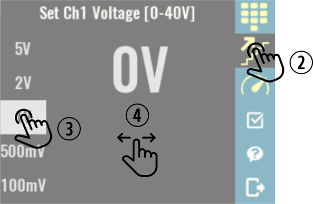
2 |
Tap on step method icon. |
|
|
3 |
Select step value or increment. |
|
|
4 |
Sliding across the main part of the window will increase (right) or decrease (left) the value of the selected parameter using the increments selected.
The encoder knob can also be used to change the value. (1 V is the selected increment in this example).
|
|
|
Slider |
|
|
|
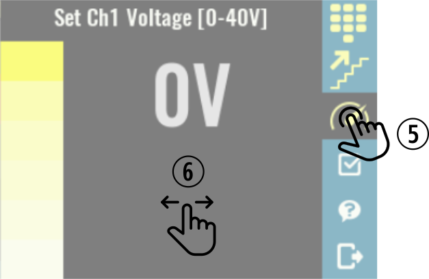
5 |
Tap on slider method icon. |
|
|
6 |
Sliding across the main part of the window will increase (right) or decrease (left) the value of the selected parameter. |
|
|
Confirmation mode |
|
|
|
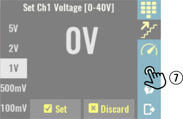
7 |
Confirmation mode blinks the new value of the setting until it is confirmed by pressing the Set button, at which point the new value is applied. The parameter value can be reset to the previous value using the Discard button.
The set and discard buttons are shown on the bottom of the screen.
To enable or disable confirmation mode tap the checkbox icon on the right.
Note: confirmation mode can be used in Step and Slider input modes only. |
|
7.4. Accessing channel protections and settings
The EEZ BB3 firmware includes comprehensive control of each power module and the feature list goes well beyond the basic operation of setting and displaying output parameters. Other channel specific functions are shown in the Protections and settings page.
The channel Protections and settings page can be reached whenever the channel is in regular or maximized view.
Note that if any of channel’s protection modes have tripped, tapping the Protection icon will take you to the Clear / Disable protection page – regardless of whether the channel is in regular of maximized view.
|
1 |
Access protections and settings in regular view
Select the channel whose settings you want to change and tap on its Protection icon.
A new page with channel’s protection section and channel settings will be displayed.
Availability of certain options depends on the channel mode (e.g. when channel is in tracking or coupling mode Calibration is disabled) and capability (e.g. DCM220 module does not have any Advanced options).
|

|
|
2 |
Exit Protections and settings page.
|
|
|
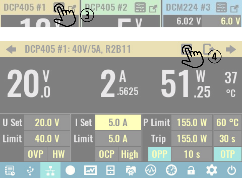
3 |
Access protections and settings from maximized view
If channel is in regular view, tap on the channel’s Maximize icon.
|
|
|
4 |
Tap on its Protection icon. |
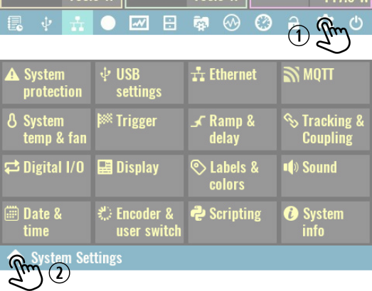
7.5. Accessing system settings
|
1 |
Tap on System settings icon on the status bar.
The number of available options depends of firmware version.
When System settings page is displayed it is still possible to check channel’s output state and values (e.g. in this example all outputs are turned off).
|
|
|
2 |
Exit System settings page. |