EEZ BB3 two channel kit assembly instructions
Introduction
Instructions presented in this document are related to BB3 – Two Channel (Full) kit offered through a crowdfunding campaign.
The EEZ BB3 kit is not an end-user product. As such, it has not been subjected to any conformance testing, and it may not comply with some or any technical or legal requirement that are applicable to finished products including, without limitation, directives regarding electromagnetic compatibility and recycling for instance (WEEE, FCC, CE or UL). Assembling and using the EEZ BB3 requires an understanding of electronic circuits and basic computer programming skills.
If you need assistance, please contact us using this form or join us on our Discord server (invitation) or post your problem on the EEVblog forum here. Or, feel free to open a New issue on GitHub here, but please check first to see whether a similar issue already exists).
The only tool required for the kit mechanical assembly is a medium Phillips head screwdriver. Of course, a multimeter for checking the wiring and voltage at a few points during assembly is recommended.
Before you start
We made our best effort to make your EEZ BB3 kit complete and functional. However, please note that due to limited resources, the kit is not completely and thoroughly tested. Basic tests were performed on the core and power modules and the cooling fan.
Modules are tested on our “testbed”, but not using a wire harness, with the AC/DC modules that come with your kit. Therefore, it’s highly recommended that you check visually, mechanically and with an ohmmeter that cables are properly assembled before you proceed with final assembly (consult the Wire harness section).
The basic testing covered communication over Ethernet, fan control, power control, touchscreen functionality, beeper, TFT display and output voltage and current programming over the full range (i.e. up to 40 V and 5 A with connected load). The AC/DC modules are capable of working with both 115 and 230 VAC.
Kit version identification
Starting in April 2021, the BB3 kit with new versions of the modules is on sale. They are most easily recognized by the blue color of the PCBs (Fig. 3) as opposed to the crowdfunding version which has green PCBs. The kit version with the new modules for simplicity will be listed below according to the MCU module version number which is r3B3 (the previous version is r2B4).
If you own the r3B3 version, consider the following:
- The SDcard comes already mounted on the MCU module. It is recommended that you remove the SDcard before mounting the front panel (Fig. 12, 13, 14).
- The holes on the front panel for the Standby LED and PE terminal can be too tight, which can make it difficult to mount the front panel because the LED indicator can move in the process from the center. If this happens carefully from the back of the front panel with a screwdriver return the LED indicator to sit in its hole.
- Your MCU module may have come with v1.6 firmware installed. If this is the case you will need to update it to v1.6.1 or later otherwise working with power modules (DCP and DCM) will not be possible (see resolved issue #172).
- The AUX-PS module (r3B5) is missing one mounting hole (above the AC inlet). Therefore for PE connection to the chassis a separate wire is used (Item R, Fig. 5)
- Top cover (Item 1, Fig. 1) has two additional holes for better fixation to the front and back panel.
Field report update (r2B4 version)
A large number of backers have already successfully completed their EEZ BB3 kit. In a small number of cases, they encountered issues with the supplied parts. The issues seen are:
- The 16-pin IDC cable may be faulty (Item F, Fig. 4). The cable problem can be detected by visual inspection, and if it is connected between the AUX-PS and the MCU module, the MCU module will not work (nothing will appear on the display, no tone will be heard). If you don’t want to wait for replacement use D89116-0031HK-3365/16-D-3 available on Digi-key.
- Missing M3 threads on 2 of the 4 holes on the Mean Well AC/DC converter mounting frame (Item 5, Fig. 1)
- One Hexagonal M3×6 mm metal spacers (Item J, Fig. 4) may be missing
- One or more M3×5 mm countersunk screws (Item M, Fig. 4) may be missing
- You can find excess M3×4 mm screws (Item L, Fig. 4)
- TFT display on enclosure front panel (Item 3, Fig. 1) came with broken glass
- Important discovery that may affect backers that has AUX-PS module r3B3 (green PCB): #108.
Feel free to contact us if you notice any defect that we can arrange a replacement.
Kit assembly steps
- Package content
- Plastic bags content
- Bottom plate
- Installing MCU and BP3C
- Connecting TFT display
- Front panel mounting
- Installing AUX-PS module
- Rear panel mounting and cable connection
- First power up and installation of power modules
- User manual and firmware update
1. Package content
The BB3 kit consists of the following parts, as shown in Fig. 1 and Fig. 2:
|
Item |
Description |
|
1 |
Pre-drilled enclosure top cover |
|
2 |
Pre-drilled enclosure bottom plate |
|
3 |
Enclosure front panel with mounted 4.3” TFT touch-screen color display |
|
4 |
Enclosure rear panel with mounted Ø80 mm cooling fan |
|
5 |
Mean Well AC/DC converter mounting frame |
|
6 |
Plastic bag with wire harness and miscellaneous mounting parts |
|
7 |
Core modules (AUX-PS, MCU and BP3C) and micro SD card |
|
8 |
DCP405 power module ×2 |
|
9 |
Mean Well 48 VDC AC/DC converter ×2 |
Please note that an AC power cord is not included with this kit.
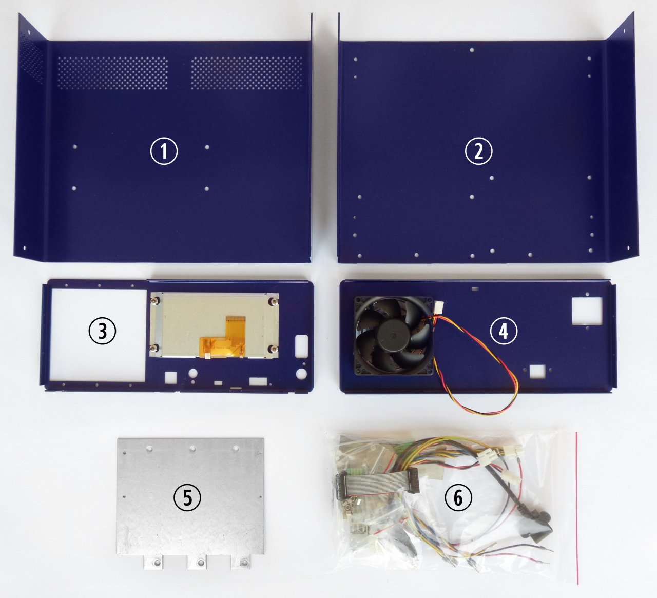
Fig. 1: BB3 kit content (r2B4)
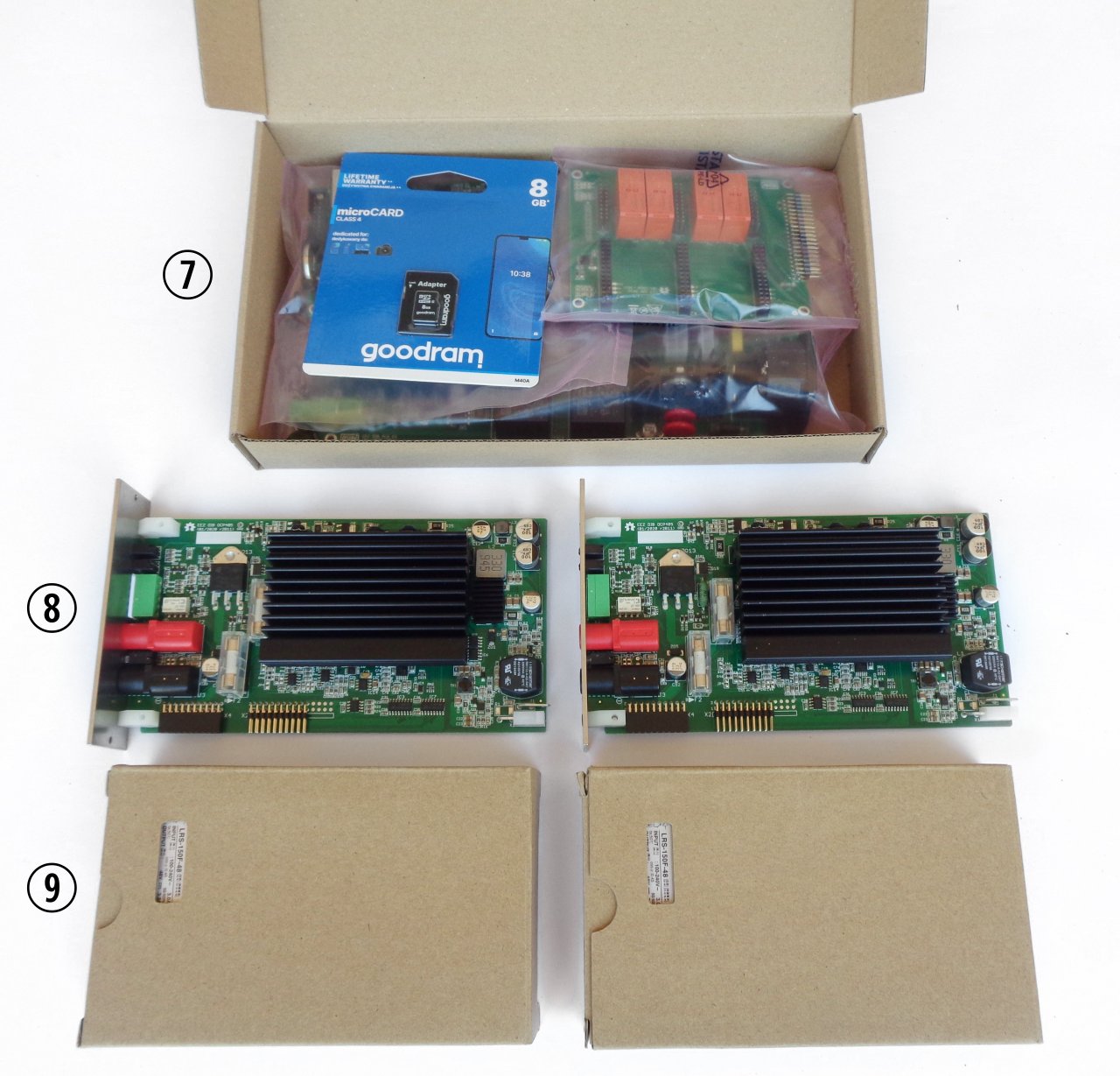
Fig. 2: BB3 kit content (r2B4 base modules, DCP power modules and AC/DC converters)
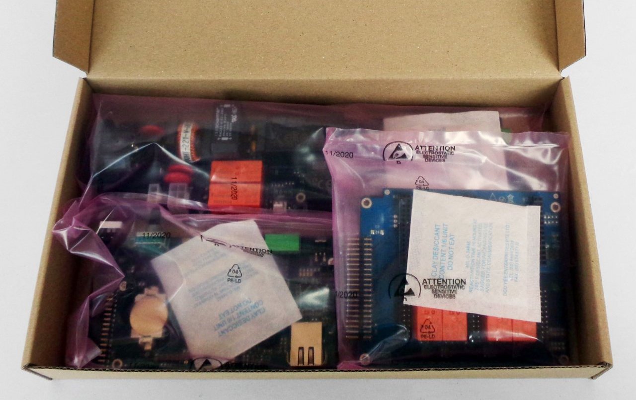
Fig. 3: r3B3 base modules (SD card is already installed on the MCU module)
2. Plastic bag contents
Before start assembly please take some time to check that the contents of the plastic bag (item 6) include everything listed below. Also familiarize yourself with the Item naming that will be used in the rest of the document.
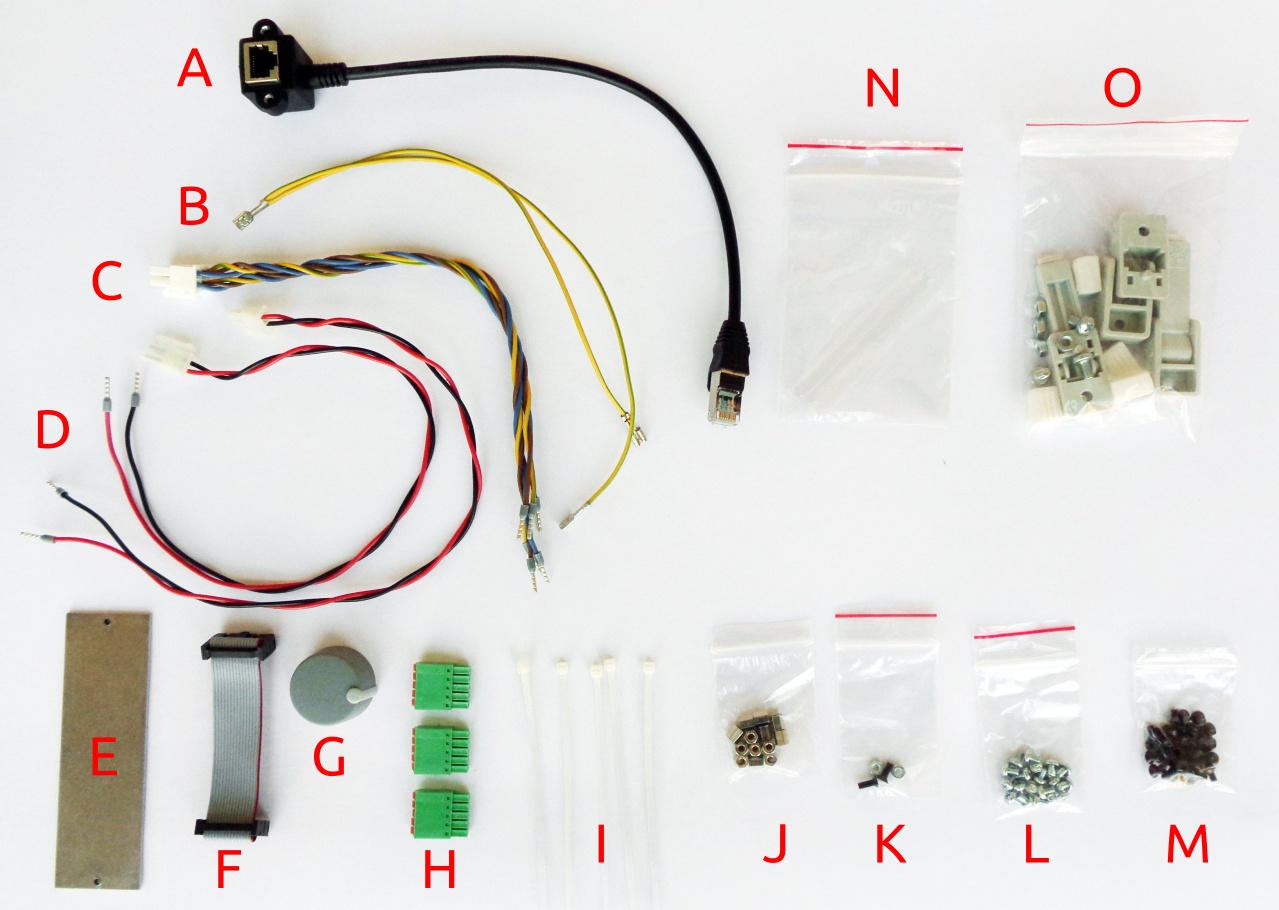
Fig. 4: Plastic bag content
|
Item |
Description |
|
A |
Ethernet patch cable |
|
B |
Dual power module PE (Protective Earth) cable |
|
C |
Dual AC/DC power module AC input cable |
|
D |
Power module DC input cable |
|
E |
Blind module front panel |
|
F |
16-pin IDC flat cable |
|
G |
Encoder knob |
|
H |
5-pin push-in connectors |
|
I |
Cable ties ×6 |
|
J |
Hexagonal M3×6 mm metal spacers ×13 |
|
K |
Mounting set for AC power inlet |
|
L |
M3×4 mm screws ×13 |
|
M |
M3×5 mm countersunk screws ×40 |
|
N |
Mean Well terminal covers |
|
O |
Enclosure feet kit |
Additionally, the r3B3 version comes with the following PE mounting kit:
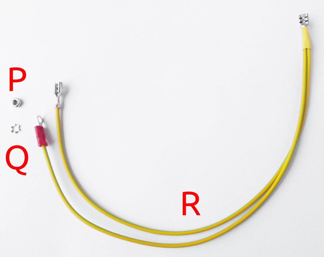
Fig. 5: r3B3 PE mounting kit
|
Item |
Description |
|
P |
Ethernet patch cable |
|
Q |
Dual power module PE (Protective Earth) cable |
|
R |
Dual PE (Protective Earth) cable for display |
3. Bottom plate
As a first step, mount the plastic feet. Identify the foot holes on the bottom plate (Fig. 6.) and unpack the content of the bag with the foot parts (item O, Fig. 4.). The front feet come with an extended part that, when mounted and folded out, can set the enclosure at an angle.
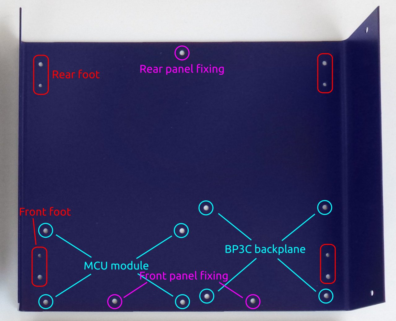
Fig. 6: Enclosure bottom plate
The M4 screws mount into the larger holes as shown in Fig. 7. Once a foot is secured, the rubber part can be pushed in to hide the screw head.
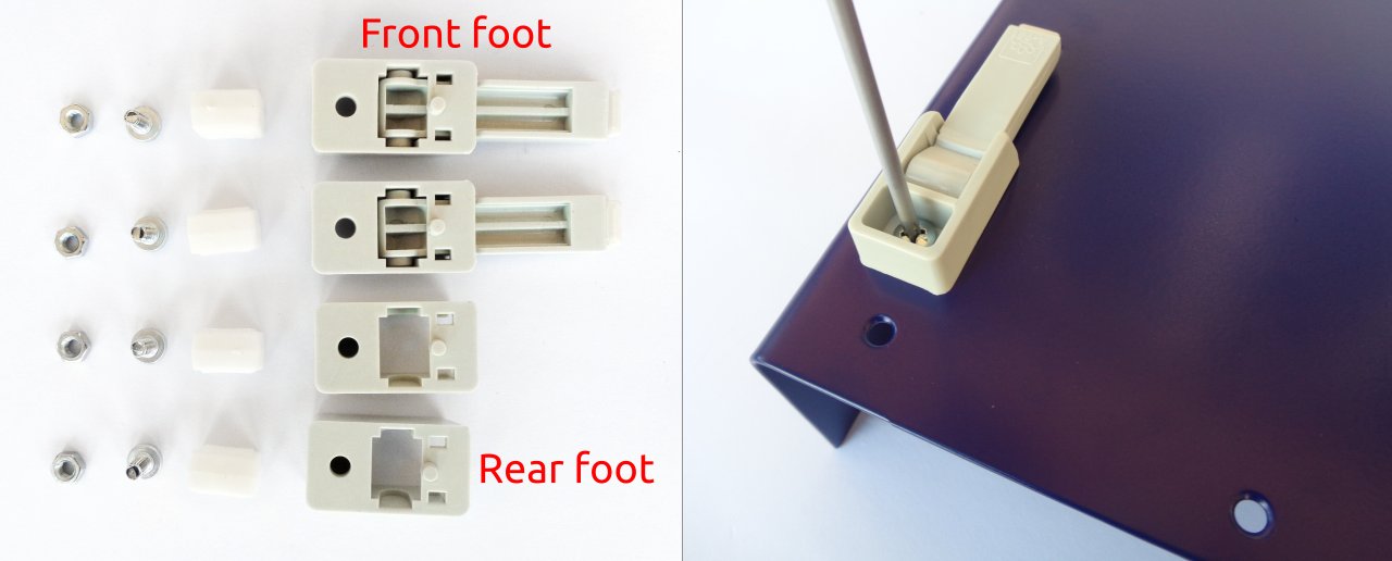
Fig. 7: Feet parts and front foot mounting
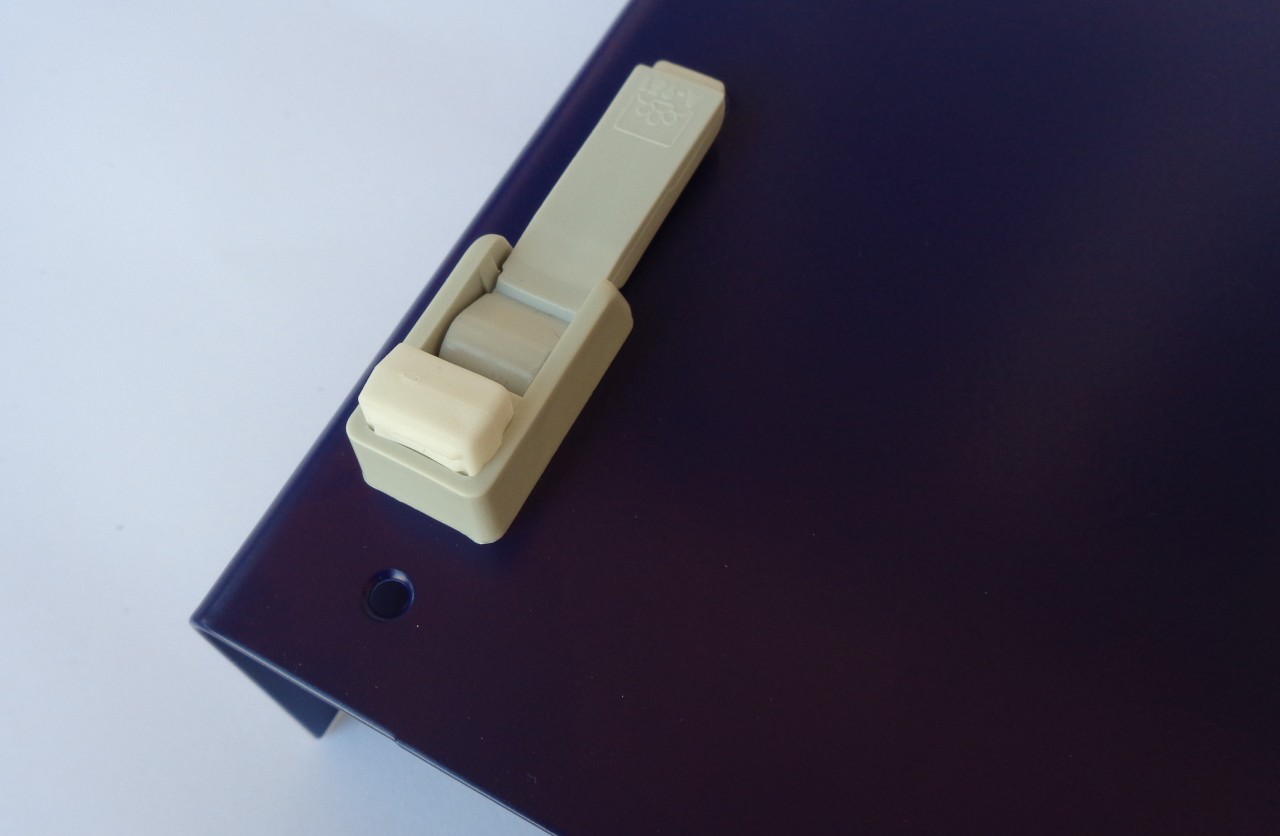
Fig. 8: Front foot mounting completed
Rubber inserts inserted to different depths may cause the bottom plate not to be leveled. If you wish to correct the leveling now, press carefully along the ends of the bottom panel until a satisfactory result is obtained. The final leveling can also be done after all the components have been installed and the top panel mounted. This is the recommended method because it is less likely to cause the bottom plate to deform during the leveling process.
4. Installing MCU and BP3C
Remove the MCU module from the package. Since it comes with a battery installed, take care to avoid short circuits from placing it on a conductive surface. Fig. 9 shows the parts (referenced by the labels in Fig. 4) required for mounting this module.
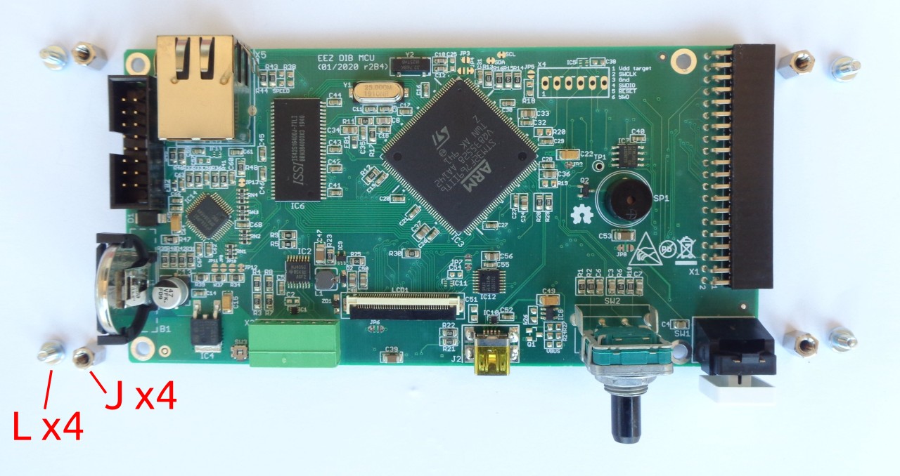
Fig. 9: MCU module r2B4 with mounting parts
Attach the hexagonal metal spacers (J) using screws (L) to the four holes at the corners of the module. Repeat the same procedure on the BP3C backplane shown in Fig. 10.
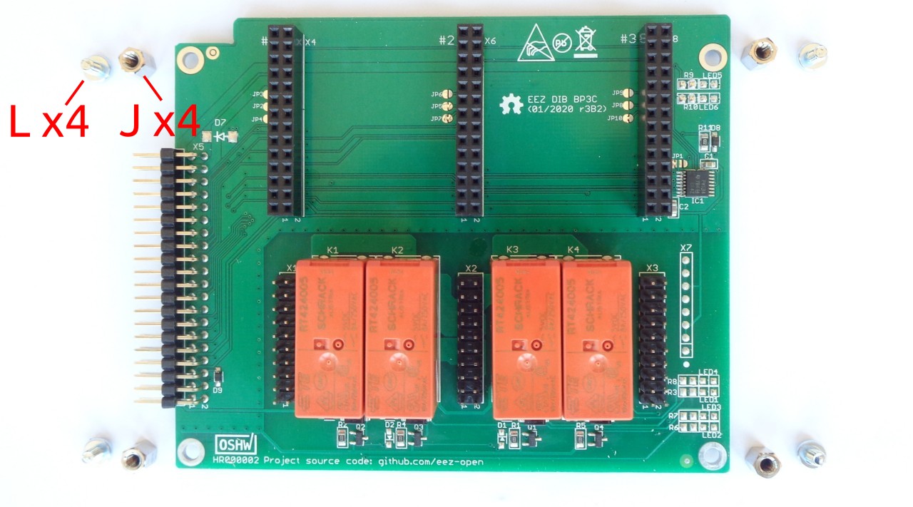
Fig. 10: BP3C backplane with mounting parts
Carefully connect the modules together (40-pin X1 socket on MCU module side and X5 header on BP3C side). You can now proceed with mounting the module to the bottom panel using screws (item M in Fig. 4) in the positions shown in Fig. 6.
Do not completely tighten these screws before installing the front panel.
5. Connecting TFT display
In order to mount the front panel to the bottom panel, it will be necessary to connect the TFT display to the MCU module, first. This is the most delicate operation in the entire EEZ BB3 assembly procedure, so it requires extra care.
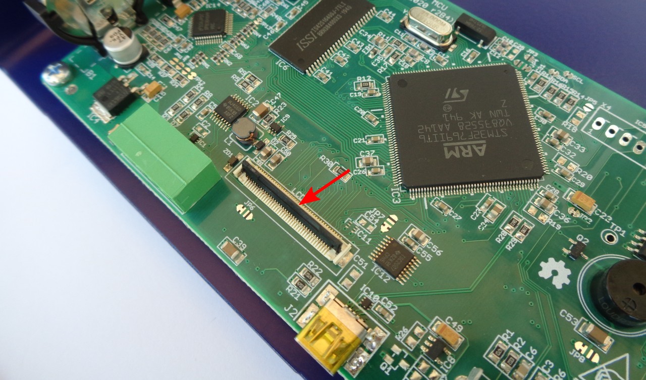
Fig. 11: 40-pin FFC display connector
First, identify the connector position on the MCU module and carefully place the black plastic lever in the up position (Fig. 11) to allow the display flat flexible cable (FFC) to enter smoothly.
Do not power on the MCU module without the display connected or with a loosely connected flexible display cable. Doing so may damage the power supply of the display backlight located on the MCU module.
6. Front panel mounting
Carefully bend the display cable so that it is in line with the FFC connector and slowly insert it (Fig. 12). When the flexible display cable is in place, lower the black lever to lock the cable (Fig. 13).
Do not force the flexible cable into the FFC connector as it may damage the cable and the connector.
Fig. 12: Inserting display flexible cable into 40-pin FFC connector
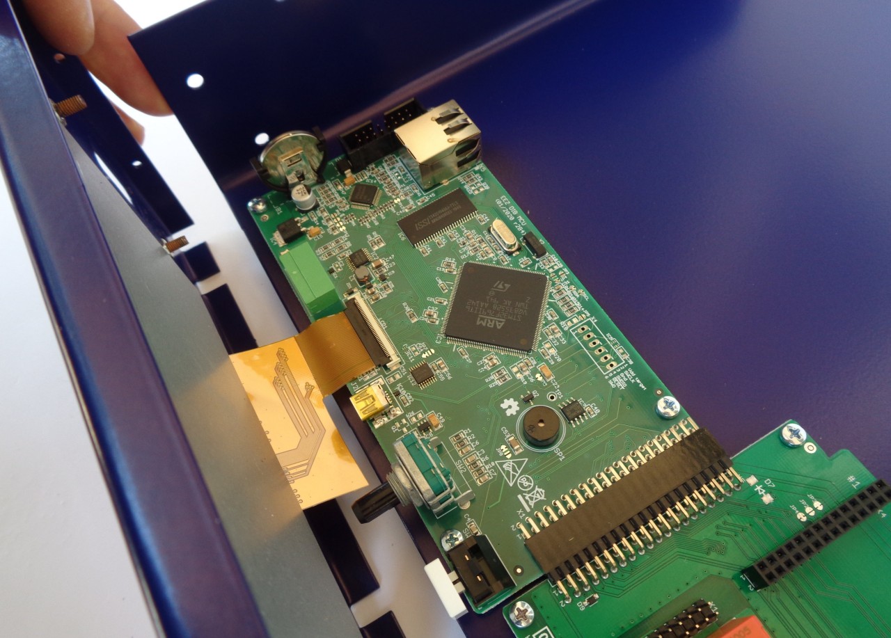
Fig. 13: 40-pin FFC connector in lock position
Before proceeding to fix the front panel to the bottom plate, check that the encoder shaft and user switch are in place (Fig. 14). Additionally, check that the user switch is functional (Fig. 15); that it is not pinched and that it can be depressed.
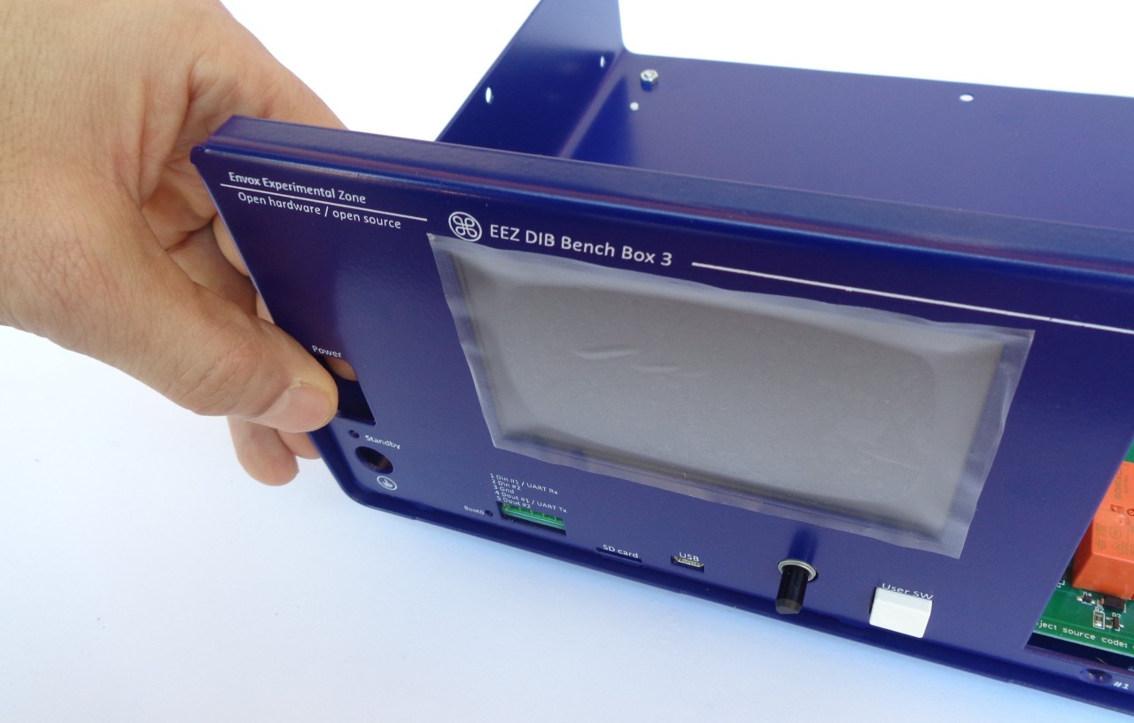
Fig. 14: Checking that the encoder shaft and user switch are in place
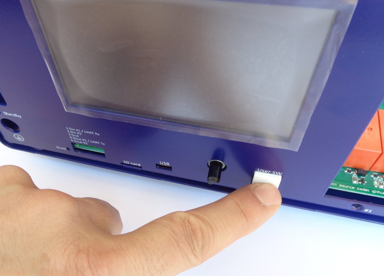
Fig. 15: Checking that the user switch works (that it is not pinched)
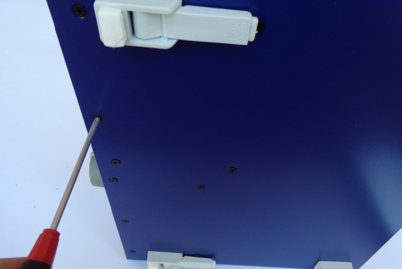
Fig. 16: Fixing the front panel from below to the bottom plate
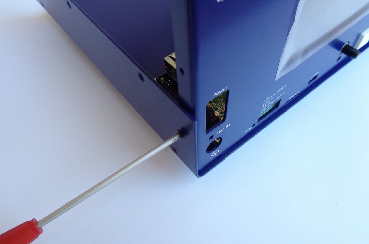
Fig. 17: Fixing the front panel from the side to the bottom plate
Fix the front panel to the bottom plate (Fig. 16) with two M3 screws (item M, Fig. 4.) in the positions shown in Fig. 6. Continue the installation by fixing the front panel to the sides of the bottom plate with another two M3 screws (item M, Fig. 4.) as shown in Fig. 17. Check again that the user switch is working and then tighten the 8 screws that hold the MCU and BP3C to the bottom plate.
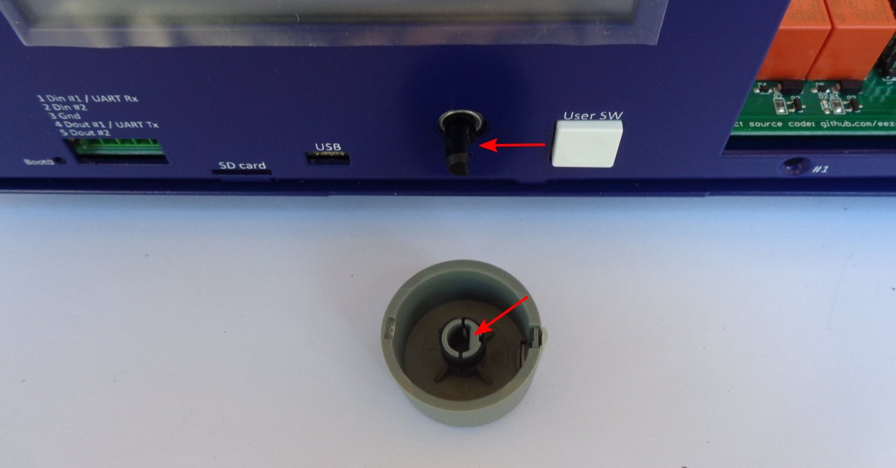
Fig. 18: Encoder knob before mounting
The encoder knob now can be mounted. Be sure to align the flat on the encoder shaft with the flat in the encoder knob recess when mounting the knob (Fig. 18).
7. Installing AUX-PS module
Remove the AUX-PS module from the package and attach the hexagonal metal spacers (J) using screws (L) in the five holes of the module.
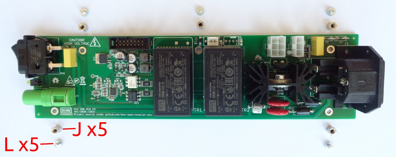
Fig. 19: AUX-PS module with mounting parts
The AUX-PS module should be attached to the rear panel with two screws and nuts (contents of bag K in Fig. 4). It is best to do this before the AUX-PS is mounted on the bottom plate so that the nuts are easier to access during mounting (Fig. 20).
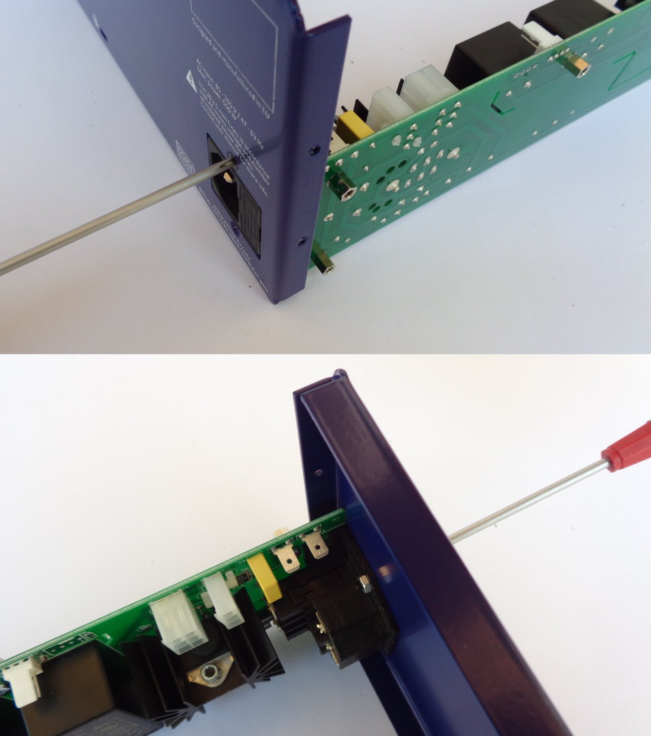
Fig. 20: Mounting AUX-PS module to the rear panel
Continue to install the AUX-PS module by carefully inserting it from the back, making sure that the standby LED and power switch locate in their holes in the front panel. When the AUX-PS module is inserted, secure it with 5 screws (item M, Fig. 4.) to the side of the bottom plate (Fig. 21).
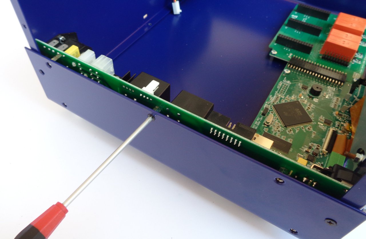
Fig. 21: Fixing the AUX-PS module on the bottom plate
For the r3B3 version, you can now connect the PE wire (item R, Fig. 5) to the AUX-PS module and attach one end to the TFT touchscreen display using item P and Q (Fig. 23). Note that item J in this case is not fixed on the other side to the AUX-PS module, but only touches it.
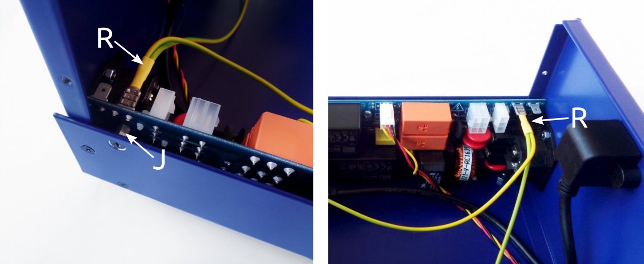
Fig. 22: r3B3 enclosure PE wiring
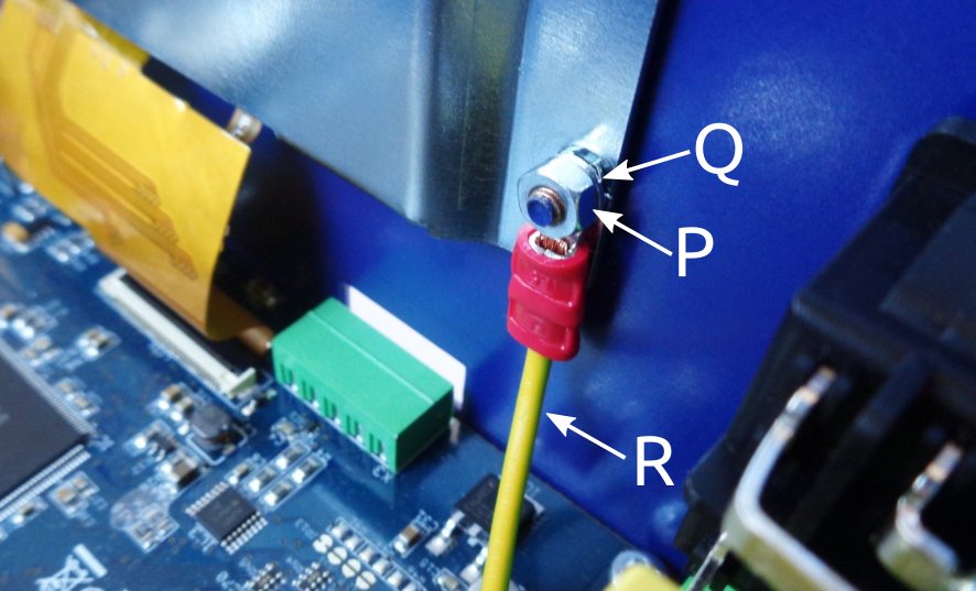
Fig. 23: r3B3 PE wire attachment to the back of the display
8. Rear panel mounting and cable connection
Attach the rear panel to the bottom plate. This will require three screws (item M, Fig. 4).
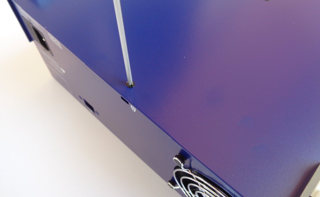
Fig. 24: Rear panel mounting
The Ethernet connection will require a patch cable (item A, Fig. 4) and two screws (item M, Fig. 4) as shown in Fig. 25.
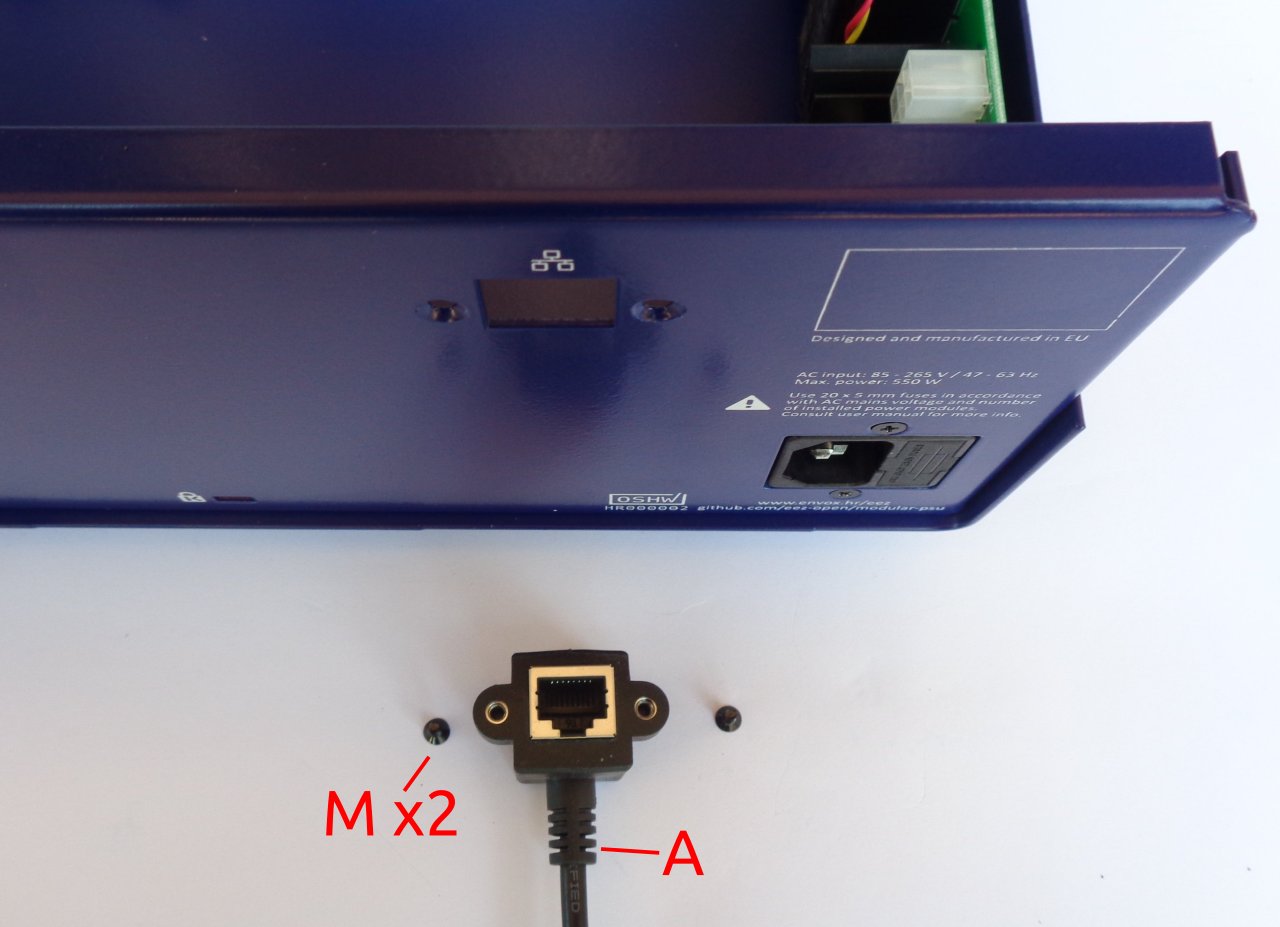
Fig. 25: Ethernet connection mounting parts
First, carefully insert the plug at one end of the Ethernet patch cable into the MCU module and then secure the other end to the rear panel. Now connect the cooling fan connector to the AUX-PS module as shown in Fig. 26. Fig. 27 shows the mounted Ethernet patch cable.
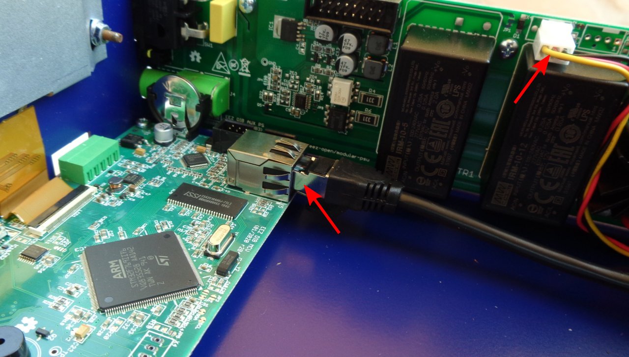
Fig. 26: Connecting Ethernet and cooling fan cables
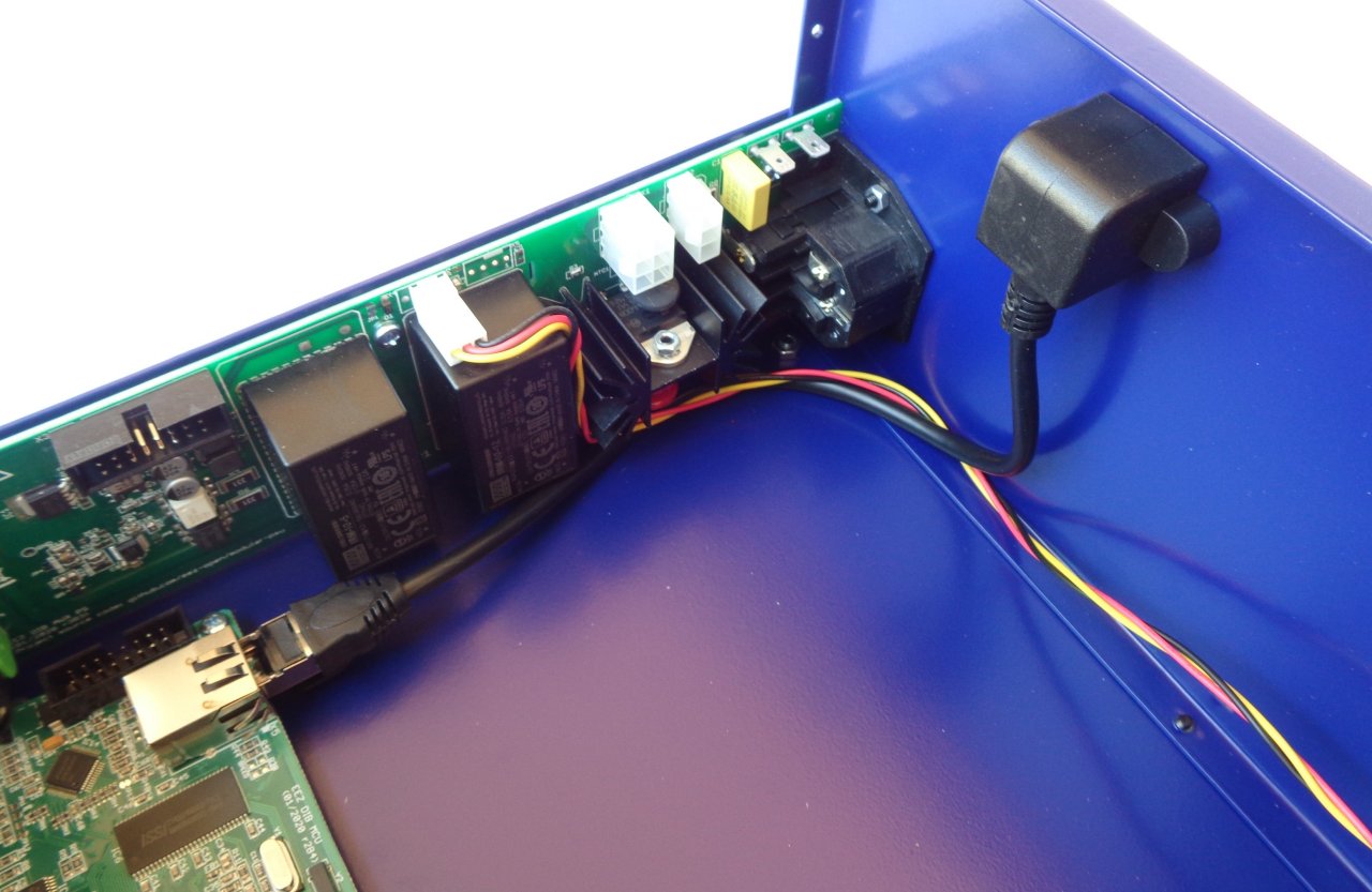
Fig. 27: Mounted Ethernet patch cable
Finally, connect the AUX-PS and MCU module with a 16-pin IDC flat cable (item F, Fig. 4) as shown in Fig. 28.
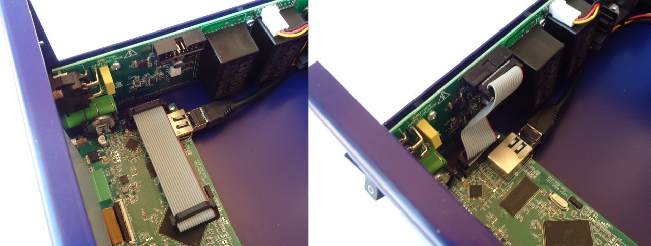
Fig. 28: 16-pin IDC cable mounting
9. First power up and installation of power modules
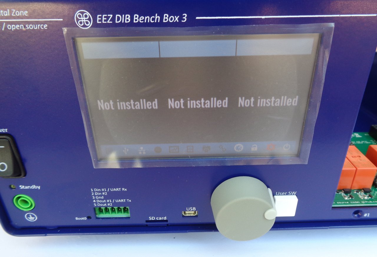
Fig. 29: Test power up without peripheral modules or micro SD card
The MCU module comes with the firmware installed. It is now possible to do a trial power-up. Connect the power cord used in your country (not included in this kit) and turn on the unit using the front panel power switch.
CAUTION: there are exposed mains voltages on the AUX PS board. Check for any foreign objects before power up and don’t touch it while power is on.
If everything is connected properly, a welcome message will appear on the display.
Ignore the "Failed" message next to "Master:" while displaying the Welcome page. It will appear because you have not inserted the SD card yet.
You can tap the red colored icon at the bottom right of the status bar to see that the micro SD card is not installed.
You can now insert the micro SD card, carefully remove it from the package and insert it as shown in Fig. 30 with the pins facing up.
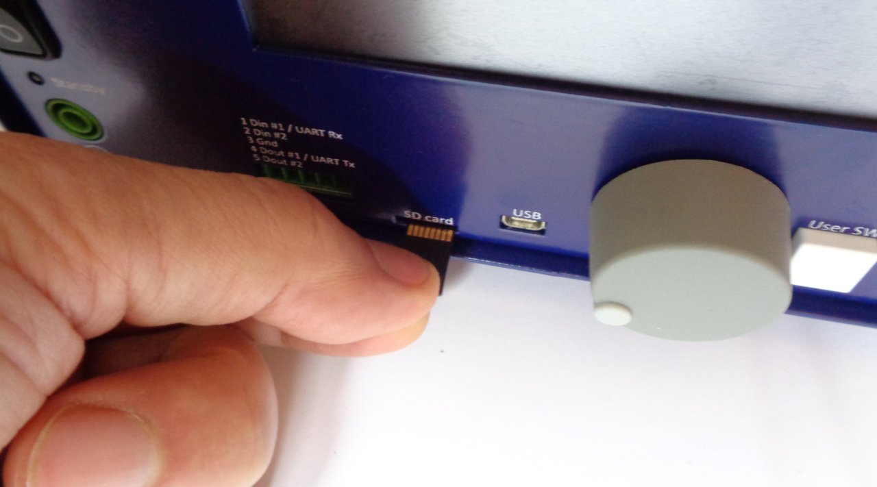
Fig. 30: Inserting micro SD card
Turn off the unit, unplug the power cord and wait 1 minute before continuing.
If you have the r3B3 kit version, make sure that the firmware v1.6.1 or later is installed before proceeding. The firmware update procedure is described in Chapter 13 of the User manual.
A number of BB3 r2B4 kits (green PCBs) are shipped with the new version of DCP405 power modules (r3B3, blue PCBs). Before proceeding with the installation of these modules, download the firmware v1.6.1 or later, otherwise BB3 will not be able to work normally (it will constantly restart).
The power modules (item 8, Fig. 2) require 48 VDC. Mean Well AC/DC converters are used for this purpose (item 9. Fig. 2). Fig. 31 shows the connecting cables and terminal covers. Note that the dual AC power cable has two arms of different lengths (Fig. 32). The shorter cable goes to the Mean Well converter that is closer to the AUX-PS module as shown in Fig. 33.
First, carefully connect the cables as shown in Fig. 32 taking note of the wire colors. When the cables are connected, the terminal covers (item N, Fig. 4) can be mounted.
|
|
|
|
AC Line |
|
|
|
|
|
AC Neutral |
|
|
|
|
|
|
Protective Earth (PE) |
|
|
||||
|
|
|
|
Vout- |
|
|
|
|
|
Vout+ |
|
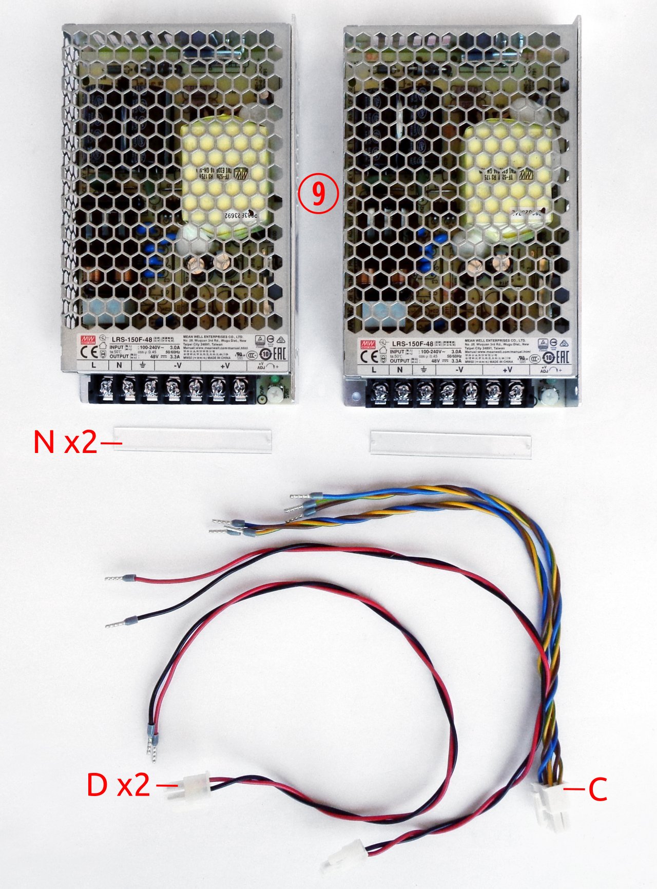
Fig. 31: Mean Well AC/DC converters and related wiring
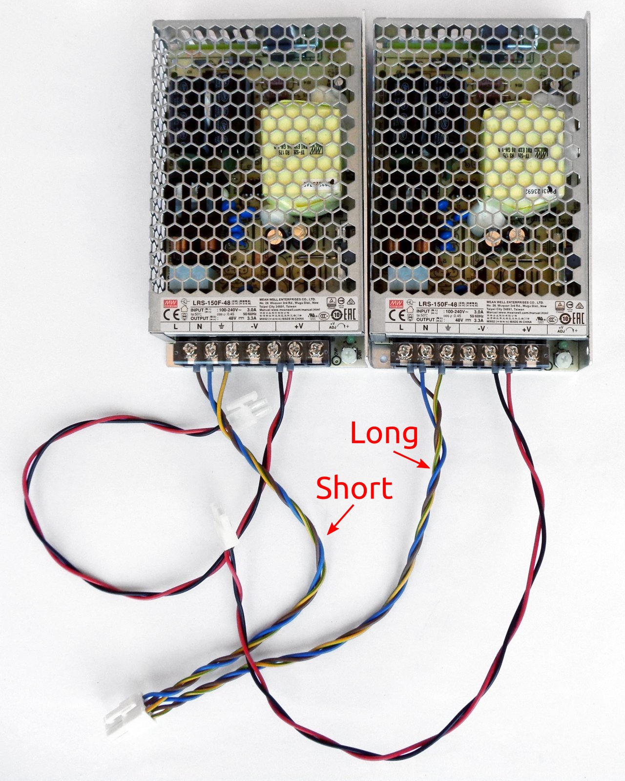
Fig. 32: Mean Well AC/DC converters with installed terminal covers and cables
The Mean Well converters are mounted on the top cover. The mounting frame (item 5) is used for this. Each converter is attached to the mounting frame with two screws (item M, Fig. 4) as shown in Fig. 33. As mentioned above, the converter with the shorter AC power cable should be mounted to the far left position.
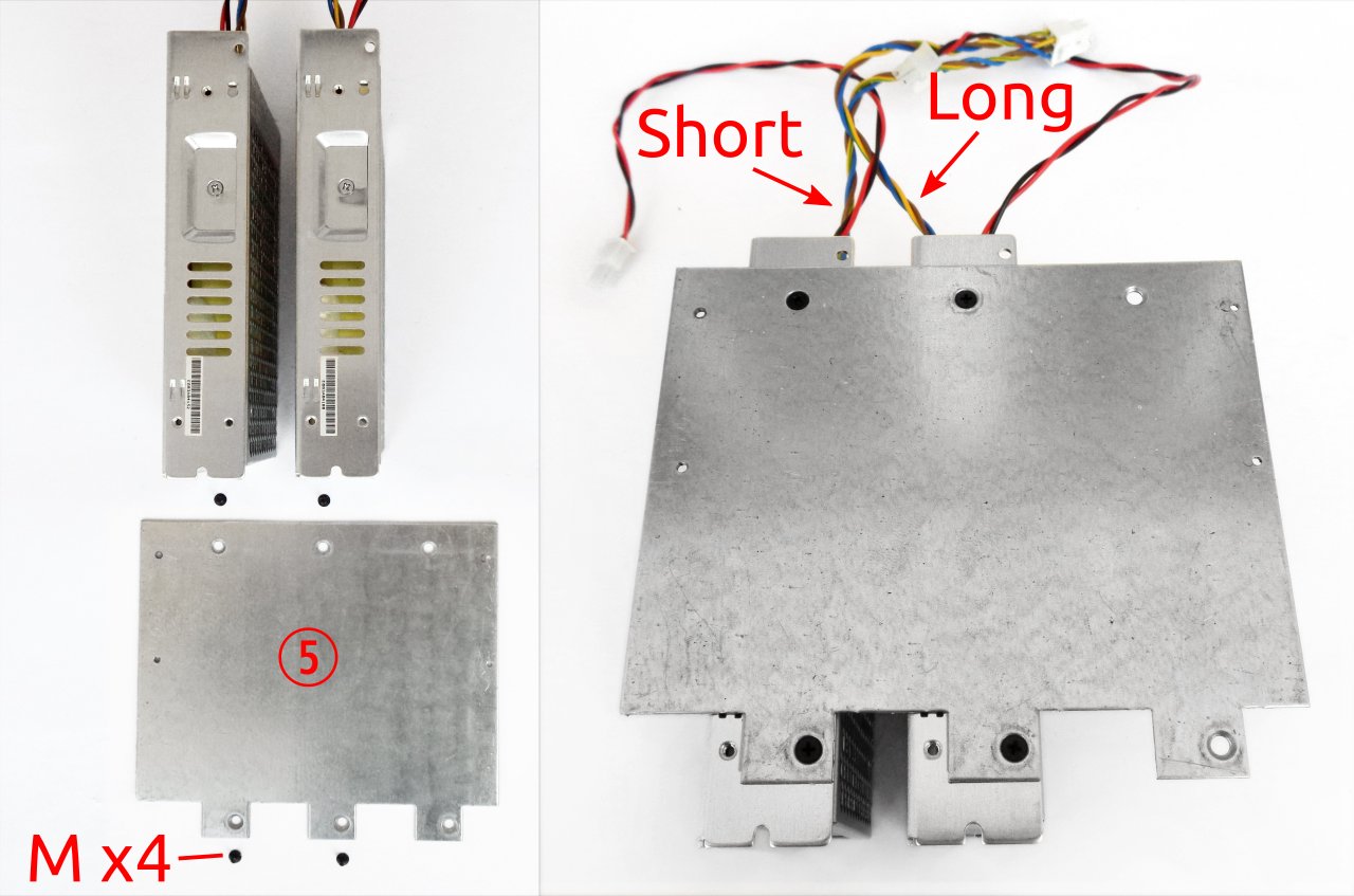
Fig. 33: Mean Well AC/DC converters with mounting frame
When the converters are attached to the mounting frame, the top cover should be placed over them as shown in Fig. 34. Secure it with four screws (item M, Fig. 4).
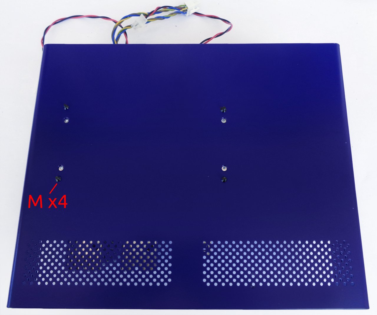
Fig. 34: Top cover placed on top of AC/DC converters
Place the top cover with the mounted converters behind the rear panel and plug the AC power connector into the AUX-PS module as shown in Fig. 35. You can now also attach the PE cable to the corresponding connector (item B, Fig. 4).
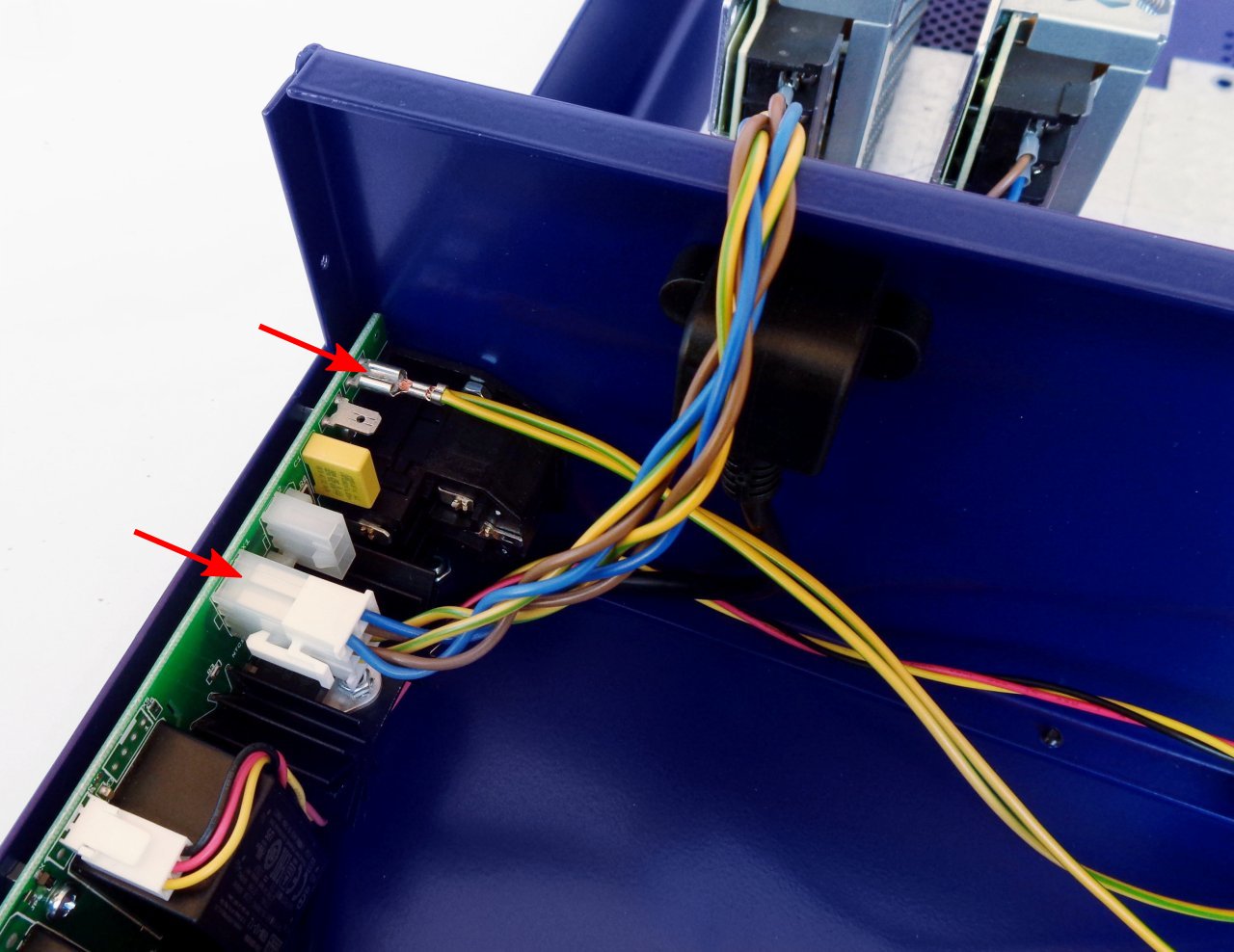
Fig. 35: AC power input and PE connections
Use cable ties (item I, Fig. 4) to secure the cables. An example is shown in Fig. 36.
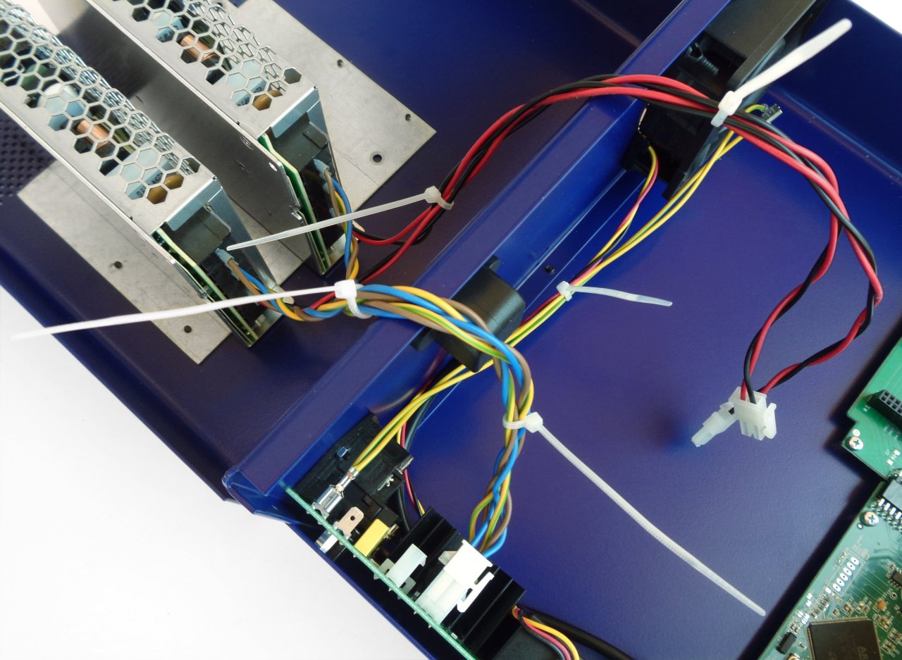
Fig. 36: Cable ties
To install the power module, four screws will be required (two for each module). Unless you have also purchased a third module, the blind front panel (item E, Fig. 4) will be used to close the third slot (Fig. 37).
The power module (item 8, Fig. 2) should be connected with the DC cable (item D, Fig. 4) coming out of the Mean Well converter and the PE cable (item B, Fig. 4) connected to the AUX-PS module as shown in Fig. 38.
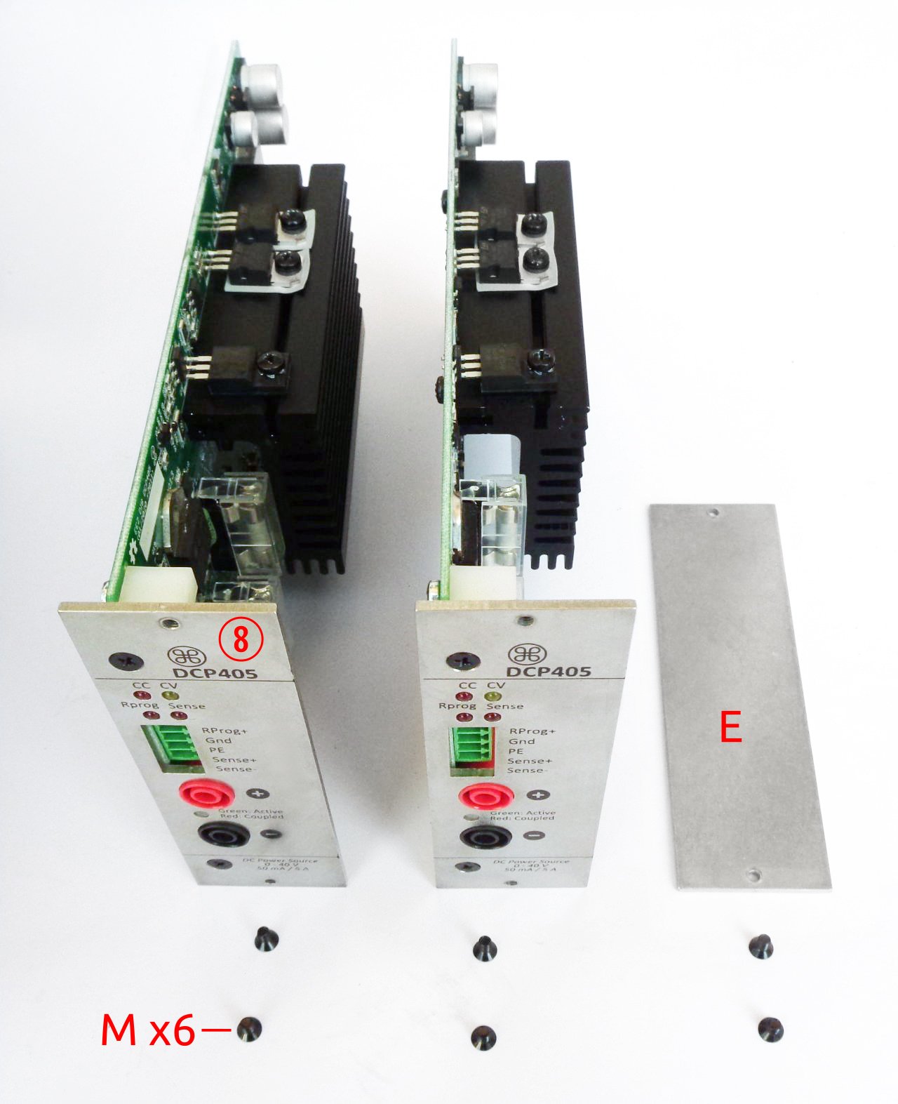
Fig. 37: Power modules mounting parts
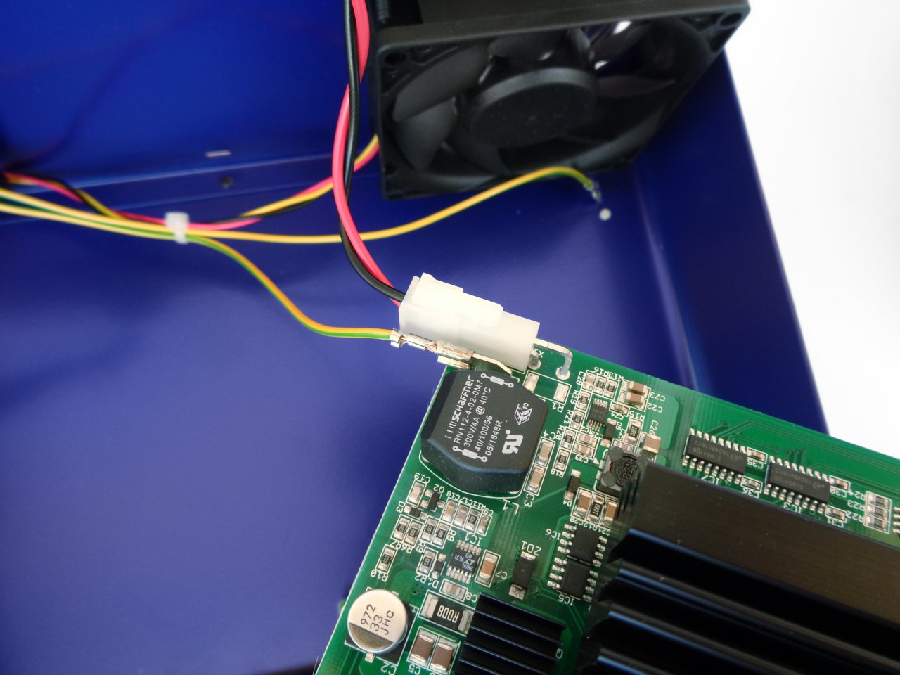
Fig. 38: Power module input connections
After connecting the power and the PE cable, insert the module into the BP3C backplane (Fig. 39)
Fig. 39: Power module insertion
Once the power module is securely inserted into the backplane slot, it should be fixed with two screws. First install the screw in the lower hole, and then a second screw into the upper hole.
Fig. 40: Power module fastening
Before closing the enclosure, make sure that the power module’s connecting cables do not interfere with the cooling fan (Fig. 41).
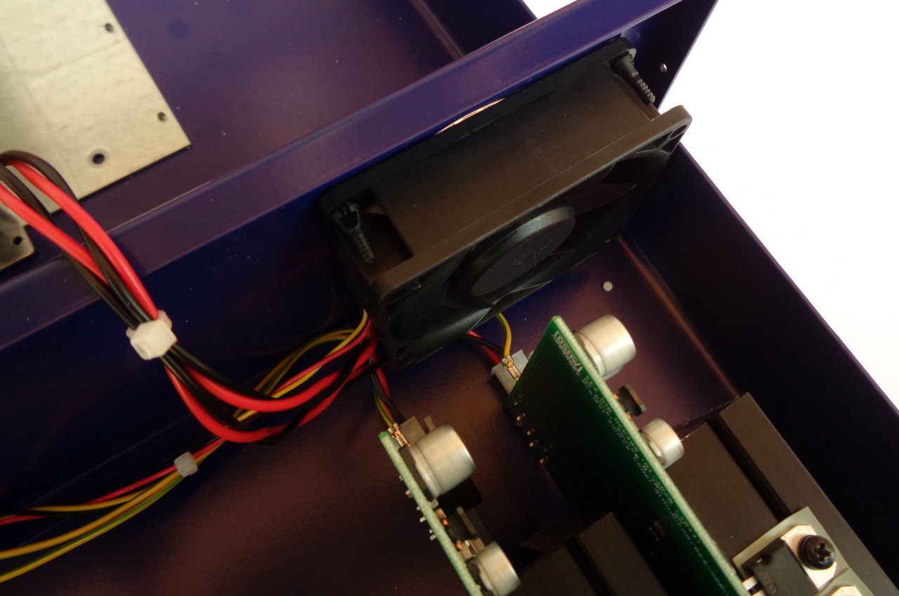
Fig. 41: Power module wiring check
Carefully fold the cables coming from the Mean Well converter and place the top cover on the enclosure. Secure it with four screws (item M, Fig. 4): first to the rear panel and then to the front panel.
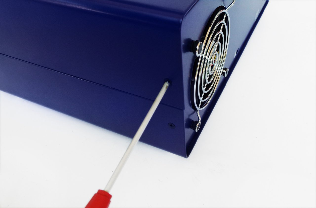
Fig. 42: Securing the top cover
10. User manual and firmware update
Turn on the power with the power switch on the front panel and if the self-test procedure is successfully completed, the start page will be displayed as in Fig. 43.
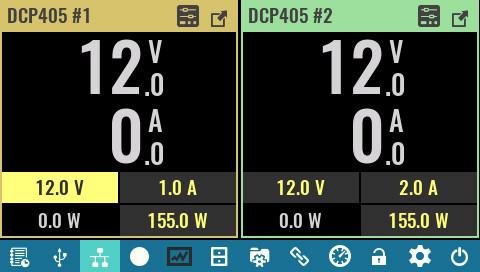
Fig. 43: Home page with two power modules initiated (firmware v1.1 or later)
The EEZ BB3 User manual is available online as well as in downloadable PDF format. For advanced users, the SCPI programming guide is also available online.
We are constantly working on firmware, removing bugs and improving it. There is a chance that the firmware that was shipped is not the most recent released version. Upgrading to the latest version is recommended. You can find information about the installed version on the System Information page or by sending a *IDN? SCPI query. You can find information about the most recent released version on the Firmware page. The firmware update procedure is described in Chapter 13 of the User manual.