5. Overview
5.1. Front panel overview
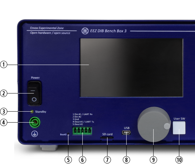
Fig. 1: Left side of the EEZ BB3 chassis front panel
|
1 |
4.3” (480 x 272) color TFT touch-screen display, 16-bit (65536) colors with brightness and luminosity control: used for local system and module specific parameter display and settings. |
|
2 |
AC mains power switch: turns the EEZ BB3 on and off. |
|
3 |
Standby indicator: on when EEZ BB3 is in standby mode (power modules AC mains power is switched off). |
|
4 |
Protective Earth (PE) 4 mm socket. |
|
5 |
Master MCU BOOT0 miniature tactile switch access hole (MCU r2B4 only): when pressed on start up the EEZ BB3 enters a special bootloader mode for system firmware uploading. |
|
6 |
Digital I/O terminals (two input and two output, protected) |
|
7 |
Micro SD card with card detection switch. |
|
8 |
5-pin USB Mini AB socket (with OTG support) |
|
9 |
Incremental encoder with switch |
|
10 |
User-defined tactile switch can be assigned to perform selected action e.g. entering inhibit mode, taking screenshot, manual triggering, etc. (see User SW). In the version with MCU module r3B3 it is also used to enter a special bootloader mode. |
5.2. Module front panels overview
The EEZ BB3 can accommodate up to three modules. An example with three power modules are shown on Fig. 2.
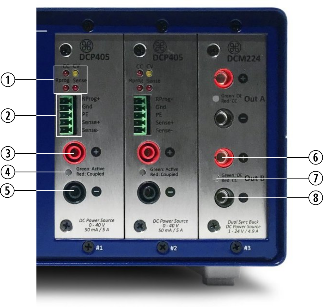
Fig. 2: Right side of the EEZ BB3 chassis front panel
|
1 |
Operation mode indicators: CC – Constant Current mode, CV – Constant Voltage mode, Rprog – Remote programming is active (DCP405 only), Sense – Remote sensing is selected (DCP405 only) |
|
2 |
Advanced options input terminals (DCP405 only): Remote programming, Remote sensing and PE. If PE is used for shielding remote sensing cable, connect it on one side only to avoid creation of ground loop. |
|
3 |
Positive output (Vout+) power connector, 4 mm, “floating” (i.e. galvanically isolated from the MCU module ground, therefore not connected to the PE potential).
Warning: The potential on this point could be up to 80 V on slot #1 when two power modules are coupled in series. |
|
4 |
OE (Output Enable) indicator, bi-color: Green – output is active and uncoupled, Red – output is active and coupled. |
|
5 |
Negative output (Vout-) power connector, 4 mm, “floating” |
|
6 |
Positive output (Vout+) power connector, 4 mm (DCM220/DCM224 only) |
|
7 |
Channel indicator, bi-color (DCM220/DCM224 only): Green – output is active in CV mode, Red – output is active in CC mode. |
|
8 |
Negative output (Vout-) power connector, 4 mm (DCM220/DCM224 only). Please note that Vout- of Ch1 and Ch2 are on the same potential but still “floating” (i.e. not connected to PE potential). |
5.3. Rear panel overview
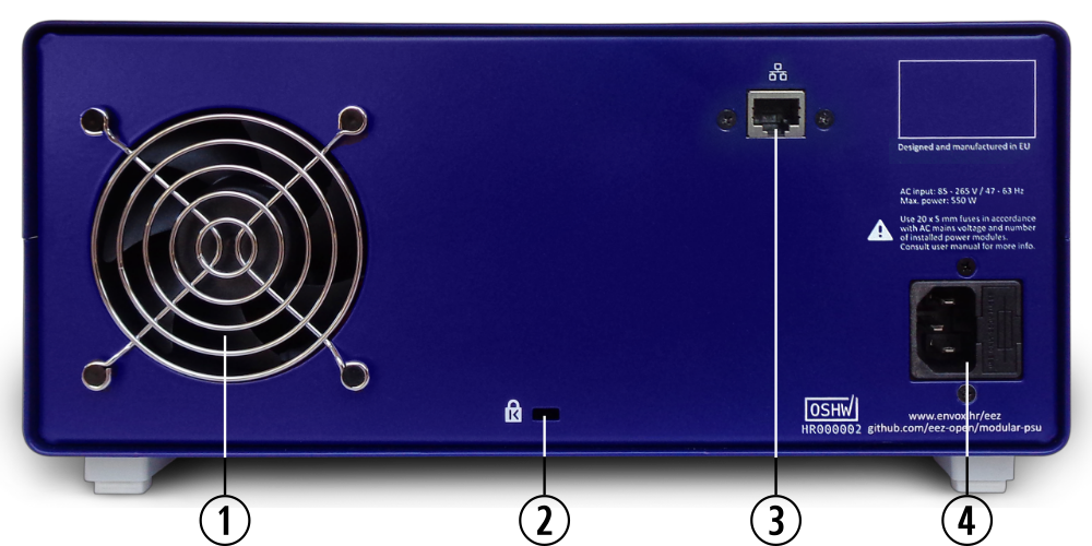
Fig. 3: The EEZ BB3 rear panel
|
1 |
Low noise Ø80 mm cooling fan with speed algorithm based on multiple temperature sensors and output current readings. |
|
2 |
Kensington Security Slot™ (K-slot) for anti-theft cable. |
|
3 |
RJ-45 Ethernet socket (10/100 Mbit/s) |
|
4 |
AC power inlet with two 20 x 5 mm fuses |
5.4. Display pages overview
The color display is used as a primary means of user interaction. Its content is dynamically rendered in order to enable quick and structured access to a multitude of system and module specific parameters. The touch-screen completely eliminates the need for specialized function keys, dedicated numeric keypad, etc. It takes no more than a couple of clicks to access any function, prioritizing access to those functions that are more important or used more frequently.
Fig. 4 shows home page of the EEZ BB3 loaded with three different power module (see Fig. 2) using the default view (numeric) for presenting output states, and measured and set values. This module configuration (i.e. DCP405 and DCM224) will be used as an example throughout this manual.
Items 1 to 3 are module specific while the rest (displayed on the status bar) are used for accessing various system options.
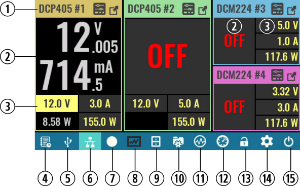
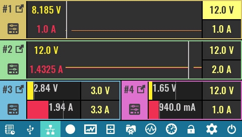
Fig. 4: Home page overview
|
1 |
Channel header: for better distinction between modules different colors are used for each header. Module name and assigned channel number are displayed together with shortcuts to channel settings (a shortcut to set or clear protection modes – If any have been tripped – and a channel “maximize” button). |
|
2 |
Channel main display section contains information about measured output voltage and current. Units of measurement are also displayed depending on the measured value (i.e. mV or V for voltage or μA, mA or A for current.
Note – this section looks different for 2-channel modules such as DCM224 due to more limited display area. |
|
3 |
Channel supplemental display section is used for set output voltage, current and power. Additionally is used for displaying measured output power together with related units of measurement (mW or W).
Note – this section looks different for 2-channel modules such as DCM224 due to more limited display area. |
|
4 |
Event view: View the event log. The icon color will change color if unread warning or error messages have been added to the log. |
|
5 |
USB activity indicator and shortcut to serial communication settings. The icon is not visible if USB/serial communication is disabled and its background becomes highlighted if USB/serial communication is established. |
|
6 |
LAN activity indicator and shortcut to the Ethernet communication settings. The icon is not visible if Ethernet communication is disabled and its background becomes highlighted if LAN communication is established. |
|
7 |
Recording / Stop: Data logger control. Use to start data logging or to stop logging before a defined end. |
|
8 |
Data log view: if logging is in progress it displays real time data. When logging is completed or stopped, it will display data from the last log. |
|
9 |
File manager: Allows access to data on a SD card such as user profiles, program lists, logged data or screenshots. Logged data and screenshots can be uploaded to EEZ Studio with one click. |
|
10 |
User profiles: 10 different profiles (with auto-recall function) are available for saving and recalling module parameters. |
|
11 |
Function generator: a simple signal generator of several predefined waveforms. |
|
12 |
Display view selection: toggle between five different presentations of output module parameters (default is numeric view – as shown on Fig. 4). |
|
13 |
Display lock/unlock: when locked all local user interaction via touch-screen display will be disabled until the same option is selected again. Unlocking is not possible without entering valid system password (the system password is not defined by default). |
|
14 |
System settings: use it to access system-wide protection settings, display, sound, trigger, digital I/O, date & time, Encoder and user switch, AUX temperature & fan control, Ethernet, Serial/USB and channels calibration |
|
15 |
Power / Reset control: allows access to standby, “soft” reset (see also *RST), “hard” reset (equivalent to power up reset) and option to turn off display |
5.5. Module display views
Five different views are available to satisfy various use cases as well as user preference for numeric or graphic representation of measured output values.
Regardless of the selected display view and color theme each channel will be represented in consistent order with its assigned color. The same convention is also used when a channel is displayed over the whole screen (e.g. in the case of Protection mode settings or the channel settings page). In those cases where a channel is maximized the channel color is visible on the status bar instead of the header area.
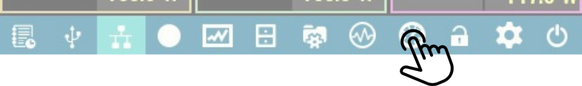
Fig. 5: Display view icon
Use icon shown on Fig. 5 to toggle between all available display views.
|
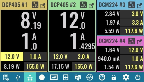
Numeric
Default display view with the largest font used to show measured voltage and current.
Output values of 2-channel modules like DCM224 are displayed with a regular font size due to lack of space.
SCPI DISPlay:VIEW 1 |
|
|
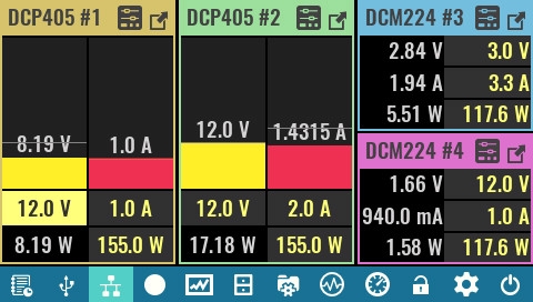
Vertical bar
This view is useful when the output values are changing rapidly.
Currently measured values are displayed with regular font size, hence user has to be closer to the EEZ BB3 to read the displayed values.
SCPI DISPlay:VIEW 2 |
|
|
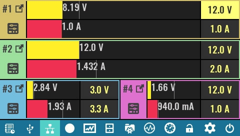
Horizontal bar
Similarly to previous view but output values are displayed as horizontal bars.
This view allows graphical presentation of the 2-channels modules, too.
SCPI DISPlay:VIEW 3 |
|
|
YT view (scan)
Similar to the previous view but a moving cursor is not used, and all data displayed moves from right to left with the speed defined by YT view sampling rate (default is 100 ms).
This type of presentation is also known as roll mode.
SCPI DISPlay:VIEW 4 |

|
|
YT view (scroll)
Measured values are displayed on the Y-axis of a 2D graph. The cursor position moves with the speed defined by YT view sampling rate (default is 100 ms).
The cursor moves cyclically – rewriting older data with new data.
SCPI DISPlay:VIEW 5 |
|
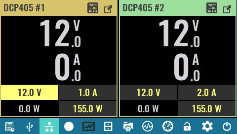
5.5.1. Two modules display view
|
When all three slots are not filled with modules, two modules display view is used otherwise one third of the screen would be unused (in that part the message Not installed would be displayed continuously). |
|
|
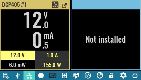
However, if only one module is installed and no maximized view is used, a Not installed message will be displayed on one half of the screen. |
|
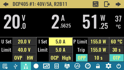
5.5.2. Maximized module view
|
Module resources can also be displayed across the entire page by selecting the Maximized view option from the module header. |
|
|
Once the maximized view is selected it is possible to navigate between the modules using the left and right arrows. The modules shown will also be in maximized view. |

|
|
The Minimized option is used to exit the maximized view. |

|