8. System settings
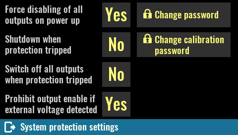
8.1. System protectionParameters in this section define channel output states on power up and options when a protection mode is tripped to prevent or reduce the possibility of damaging the connected loads.
Additionally, the system password that is used to unlock the display and calibration password can be defined or changed here.
|
|
|
Force disabling of all outputs on power up Active by default this option ensures that all channel outputs will be switched off on power up to prevent connected loads from being damaged unintentionally.
SCPI SYSTem:PON:OUTPut:DISable ON
|
|
|
Shutdown when protection tripped When selected, any protection mode that is tripped on any channel will automatically put the EEZ BB3 in standby mode.
SCPI SYSTem:POWer:PROTection:TRIP ON
|
|
|
Switch off all outputs when protection tripped Similar to the previous option except instead of entering standby mode all channel outputs will be turned off.
SCPI OUTPut:PROTection:COUPle ON
Prohibit output enable if external voltage detected DCP405 power module only: active by default this option enables the voltage on the output terminals to be monitored even when the output is disabled. When it is active, the output cannot be turned on as long as the measured voltage is greater than 500 mV.
It is strongly recommended that this option be active when the DCP405 module is used to charge batteries. In this case, it will not be possible to enable power output with the battery connected, because that will lead to an OVP trip, and if HW OVP is selected, it may damage the crowbar circuit. This option will force you to first enable the output and only then connect the battery you want to charge.
SCPI OUTPut:PROTection:MEASure ON
|
|
|
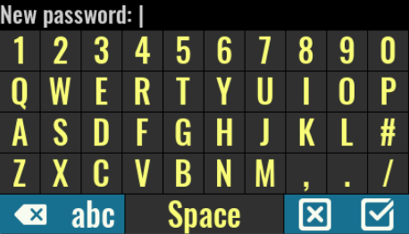
Change password The system password is used to unlock the display. By default system password is not defined (“”) and it may contain up to 16 characters. Minimum length is 4 characters. The new password is automatically stored in non-volatile memory.
When selected an on-screen keyboard will appear. Characters entered will be replaced with * shortly after entry. The new password has to be entered twice.
|
|
|
SCPI SYSTem:PASSword:NEW {<old>}, {<new>} |
|
|
Change calibration password The calibration password is used to secure access to calibration data. Unlike a system password this password is defined by default (eezbb3) and has to be entered first before new password can be entered. The calibration password may contain up to 16 characters. Minimum length is 4 characters. The new password is automatically stored in non-volatile memory.
SCPI CALibration:PASSword:NEW {<old>}, {<new>} |
|
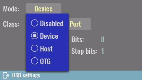
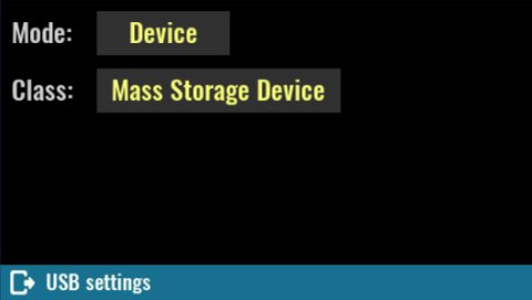
8.2. USB settingsMode Defines the operating mode or turns off the USB interface.
SCPI SYSTem:COMMunicate:ENABle {<bool>}, USB SYSTem:COMMunicate:USB:MODE |
|
|
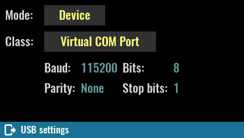
Virtual COM Port Defines activity of the serial interface over USB connection (i.e. Virtual COM port). When selected serial communication parameters will be displayed (Baud, Bits, Parity and Stop bits).
SCPI SYSTem:COMMunicate:USB:CLAss VCOM
|
|
|
Mass storage device When this class is selected the operating system of the connected computer will see the installed SD card as a mass storage device. It will be possible to work with the SD card as well as other disks (browse, read, write, delete, create new folders, rename, etc.)
The selection of this class will be valid until the next restart when it will return to Virtual COM port again.
|
|
|
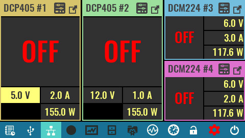
IMPORTANT: when the SD card is in this mode, EEZ BB3 cannot save events to log, access file manager, user profiles, etc. For this reason, there will also be disabled icons in the status bar, and the system settings icon will turn red because the status of the SD card will change to Not present.
SCPI SYSTem:COMMunicate:USB:CLAss MSTO |
|
|
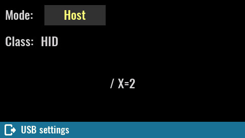
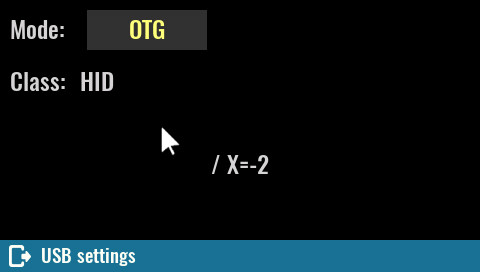
Host When this mode is selected the EEZ BB3 provides VBUS power for connected USB device (e.g. mouse, keypad, foot pedal, etc.). The USB Class will be automatically set to HID.
USB mouse (wired or wireless) is supported and if connected, the cursor will appear and information on the cursor coordinates will be displayed.
The USB keyboard is partially supported so that the following functions are enabled: |
|
SCPI SYSTem:COMMunicate:USB:MODE HOST |
|
|
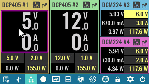
When a USB mouse is used for navigation, the clickable item on which the cursor is positioned will get a magenta box. |
|
|
OTG “On-the-go” mode allows detection of USB ID pin (set by USB cable or adapter) and adopt its USB mode and class in accordance with detected device. For example if mouse is connected with OTG adapter cable, the USB Mode will be set automatically to Host and Class to HID and mouse cursor will appear.
SCPI |
|
|
SYSTem:COMMunicate:USB:MODE OTG |
|
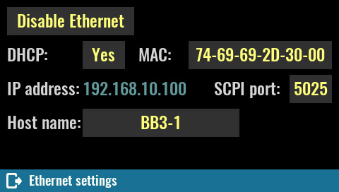
DHCP
Enable or disable the DHCP mode. In DHCP mode, the DHCP server in the current network assigns network parameters (IP address, DNS address, Gateway address and the Subnet mask). Assigned IP address will we displayed, and cannot be changed.
When DHCP is disabled all network parameters have to be entered manually using the Edit static address as described below.
SCPI
SYSTem:COMMunicate:ETHernet:DHCP {<bool>}
MAC
Defines Ethernet MAC address, a unique identifier assigned to Ethernet interface for communications at the data link layer of a network segment.
Any combination of six hexadecimal values is allowed separated by “-”. The Ethernet connection will work as long as two different machines in the LAN don’t have the same MAC address.
SCPI
SYSTem:COMMunicate:ETHernet:MAC {<mac_address>}
SCPI port
Defines Ethernet communication port for SCPI connections. Default port is 5025.
SCPI
SYSTem:COMMunicate:ETHernet:PORT {<number>}
Host name
Defines local area network (LAN) connection unique host name. Host name could contains up to 63 alphanumeric characters. “-” is allowed only if is not used as the first character. Space is not allowed and default name is EEZ-BB3.
SCPI
SYSTem:COMMunicate:ETHernet:PORT {<number>}
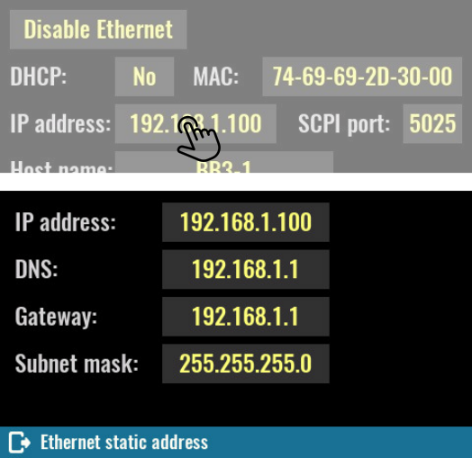
8.3.1. Static LAN settings (DHCP disabled)
|
The parameters that follows should be defined when DHCP is not selected. All values should be specified in IPv4 address format (four values from 0 to 255 separated by dots).
IP address Static local area network (LAN) address of the BB3.
SCPI SYSTem:COMMunicate:ETHernet:ADDRess {<ip_address>}
DNS IP address of the DNS (Domain Name Service) server that translates domain names into IP addresses.
SCPI SYSTem:COMMunicate:ETHernet:DNS {<ip_address>} |
|
Gateway
IP network gateway address for accessing the EEZ BB3 from outside the current sub-network.
SCPI
SYSTem:COMMunicate:ETHernet:GATEway {<ip_address>}
Subnet mask
IP network subnet mask. The subnet mask is used to determine if a client IP address is on the same local subnet.
SCPI
SYSTem:COMMunicate:ETHernet:SMASk {<mask>}
SCPI
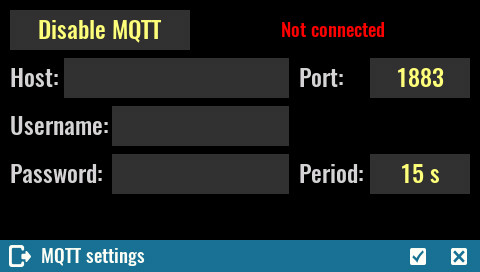
SYSTem:COMMunicate:MQTT:SETTings {<address>}, {<port>}, {<user>}, {<password>}, {<period>}
SCPI
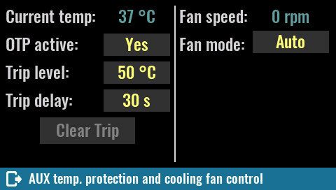
SYSTem:TEMPerature:PROTection:STATe
Trip level
Set the over-temperature protection (OTP) value in degrees Celsius (oC). Default value for this sensor is 45 oC.
SCPI
SYSTem:TEMPerature:PROTection {<temperature>}
Trip delay
Specifies how long the temperature should be equal to or higher than the set trip level for the protection to activate.
SCPI
SYSTem:TEMPerature:PROTection {<temperature>}
Clear trip
When protection is activated (tripped), this condition will be latched and further usage of the EEZ BB3 will be disabled until protection is cleared.
SCPI
SYSTem:TEMPerature:PROTection[:HIGH]:CLEar
Fan speed
Current fan speed indicator stated in rpm (revolutions per seconds). The diagnosed fan fault will be also displayed here.
Fan mode
The fan is controlled by default with firmware algorithm (Auto mode) that takes into account measured temperature on all temperature sensors and measured output currents (i.e. the higher the output current, the sooner the fan speed will increase).
Manual mode can be selected for e.g. fan testing purpose when firmware speed control algorithm is completely bypassed.
Set speed to
This option becomes available when manual mode is selected. Default value is 100 % (full speed).
SCPI
SYSTem:FAN:STATus?
SYSTem:FAN:SPEed?
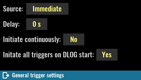
8.6. General trigger settingsThe BB3’s triggering system allows a change in output state, voltage and current or start internal data logging when receiving a trigger from selected trigger source.
One common triggering system is used to control all available channels, but will only affect those channels that are not in Fixed trigger mode (see Channel trigger settings for channel trigger mode settings). |
|
|
Source
|
|
|
|
SCPI
TRIGger[:SEQuence]:SOURce {<source>}
Delay
Sets the time delay between the detection of an event on the specified trigger source and the start of any corresponding trigger action on the channel output.
SCPI
TRIGger[:SEQuence]:DELay {<delay>}
Initiate continuously
This option defines whether the trigger system is continuously initiated or not. When set to OFF, the system remains in the IDLE state until it is set to ON or an INITiate:IMMediate command is received.
Once it is set to ON, the trigger system will be initiated and exit the IDLE state. On completion of each trigger cycle, the trigger system immediately commences another trigger cycle without entering the IDLE state.
When this option is set to OFF, the current trigger cycle will be completed before entering the IDLE state. The return to IDLE also occurs as the result of an ABORt or *RST command.
SCPI
INITiate:CONTinuous {<bool>}
Initiate all triggers on DLOG start
This option allows all resources for which the trigger is not set to Fixed to be activated with the start of data logging. Once data logging starts, it is possible to change the trigger mode of resources without affecting data logging.
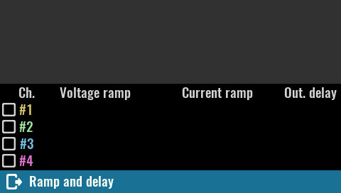
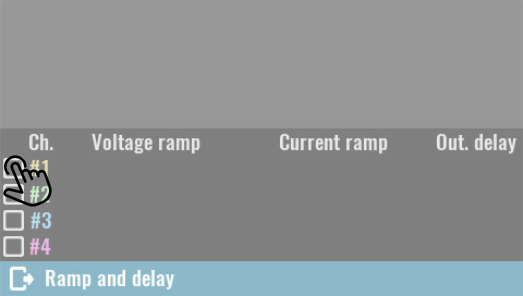
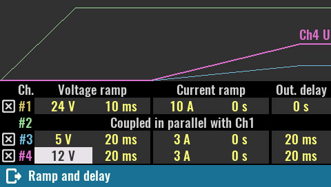
8.7. Ramp & delayThis page will show all output channels that have support for ramp and delay. |
|
|
Select the channel you want to define ramp and delay settings for.
|
|
|
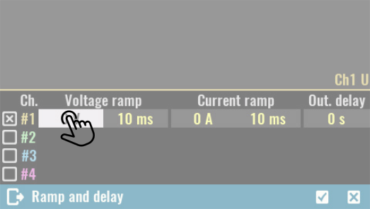
Tap on the parameter that you want to set (e.g. voltage).
|
|
|
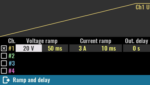
The graph above the list shows the output profile of the selected channel.
|
|
|
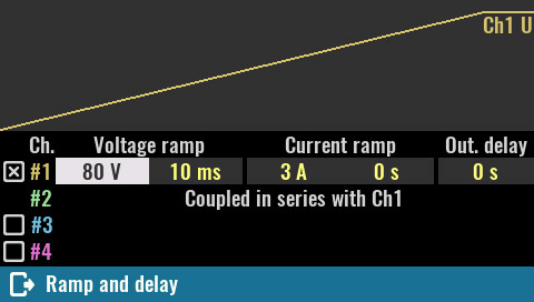
The channel list will reflect coupling in series. For example, the voltage ramp is able to be set at twice the value (up to 80 V).
|
|
|
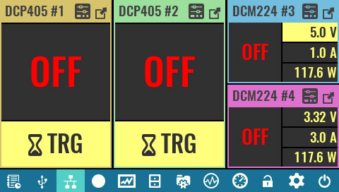
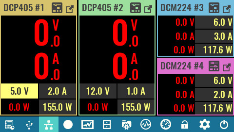
This screenshot shows an example of a complex ramp and delay setup where the first two output modules are coupled in parallel and the last two modules turn on after a delay of 20 ms.
|
|
|
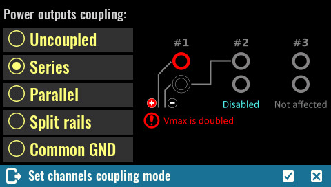
Series Coupling is series is only possible between DCP405 modules on the first two slots. When coupled, the output connectors of the module in slot 2 will be disabled, and the output voltage on the connectors of the module in slot 1 will be able to be set to twice the value (i.e. 80 V for DCP405).
The maximum output current will remain unchanged (5 A).
|
|
|
Access to the module in slot 2 will be disabled on display. All set and measured output voltage and power values shown on the display for the module in slot 1 will be doubled.
Please note that according to many standards, voltage of 50 V and above are considered to be hazardous regardless of additional factors such as air humidity and temperature, skin moisture, etc. Take all necessary precautions when the set output voltage exceeds this value.
SCPI INSTrument:COUPle:TRACking SERies |
|
|
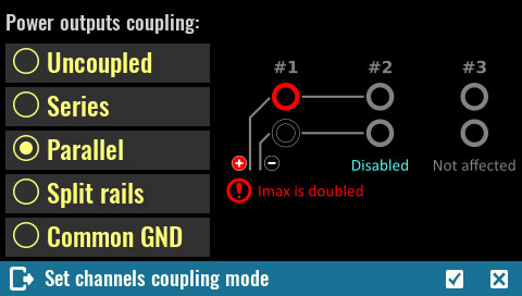
Parallel Coupling is parallel is only possible between DCP405 modules on the first two slots. When coupled, the output connectors of the module in slot 2 will be disabled, and the output current on the connectors of the module in slot 1 will be doubled (i.e. 10 A for DCP405).
The maximum output voltage will remain unchanged (40 V).
|
|
|
Access to the module in slot 2 will also be disabled on display. The set and measured output current and power values shown on the display for the module in slot 1 will be doubled.
SCPI INSTrument:COUPle:TRACking PARallel
|
|
|
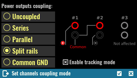
Split rails This type of coupling is similar to serial coupling except the output of both channels is still active and the coupling between the first and second channels is used as a common ground. In this way, a symmetrical output is obtained where Vout + of the first channel represents a positive rail and Vout of the second negative rail.
|
|
|
Channels can still be individually controlled, but since this configuration often requires the same output values (e.g. for powering operational amplifiers) a default is offered that places these two channels into a tracking group.
SCPI INSTrument:COUPle:TRACking SRAil
|
|
|
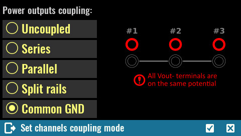
Common GND This is the simplest way of coupling the output and results in the connection of Vout- all channels on all slots to a common potential. As mentioned in the beginning, the Vout- coupled output potential will still not be at the MCU ground or PE potential.
This coupling is not required for Vout- connections between two channels on the DCM220 or DCM224 because they are already internally connected.
|
|
|
SCPI INSTrument:COUPle:TRACking CGND |
|
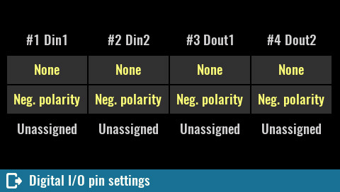
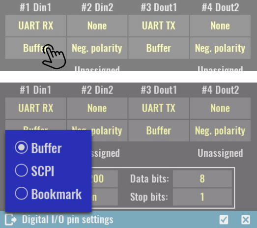
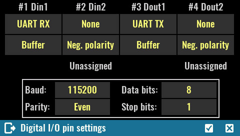
8.9. Digital I/O settingsTwo protected/buffered digital input pins plus two digital output pins are available on the EEZ BB3 front panel. Their function and polarity can be set on this page which also displays their current state.
Function Input pins may be assigned with one of the following functions:
|
|
|
|
Output pins could be assigned with one of the following functions:
- Output – The pin is in digital output mode.
- Fault – pin functions as an isolated fault output. The fault signal is true when any output is in a protected state (from OCP, OVP, OTP, OPP) or Fan fault is detected.
- Channel ON couple – pin synchronizes channel output state.
- Trigger output – This allows a BUS trigger to be sent to any digital port pin that has been configured as a trigger output. A trigger out pulse (100 ms) is generated when the state is on and a bus trigger is received. A BUS trigger is generated using the *TRG command.
- PWM – (Dout2, pin 4 only) when selected, a square wave will be generated with set frequency from 0.03 Hz to 5 MHz and duty from 0 to 100 %.
- UART TX – The pin becomes a UART transceiver (see subsection 8.10.1 below).
SCPI
SYSTem:DIGital:PIN<n>:FUNCtion {<function>}
SYSTem:DIGital:OUTPut:PWM:FREQuency {<pin>}, {<frequency>}
SYSTem:DIGital:OUTPut:PWM:DUTY {<pin>}, {<duty>}
Polarity
- Pos – a logical true signal is a voltage high at the pin. For trigger inputs and outputs, positive means a rising edge.
- Neg – a logical true signal is a voltage low at the pin. For trigger inputs and outputs, negative means a falling edge.
SCPI
SYSTem:DIGital:PIN<n>:POLarity {<polarity>}
State
Current state of all digital inputs and outputs are displayed in this section. If the pin function is not yet defined, the displayed state will be Unassigned.
SCPI
SYSTem:DIGital:INPut:DATA? {<pin>}
SYSTem:DIGital:OUTPut:DATA? {<pin>}
SCPI
SYSTem:COMMunicate:UART:MODE {<uart_mode>}
SYSTem:COMMunicate:UART:RECeive?
SYSTem:COMMunicate:UART:TRANsmit {<string>}
|
Baud: Communication speed in bits per second (baud). Select from a list of available speeds.
Data bits: Data size in bits. Select from a list of available sizes.
Parity: Parity check, could be None, Even or Odd.
Stop bits: Number of stop bits, select 1 or 2. |
|
SCPI
SYSTem:COMMunicate:UART:BAUD {<baud>}
SYSTem:COMMunicate:UART:DATA {<data>}
SYSTem:COMMunicate:UART:PARIty {<parity>}
SYSTem:COMMunicate:UART:STOP {<stop>}
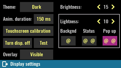
8.10. Display settingsDisplay color theme selection, brightness, luminosity, animation duration and status of display can be selected on this page.
An option for entering screen calibration (that is run by default on first start) is also available.
|
|
|
Theme The EEZ BB3 comes with three color themes that apply to every page. The default theme is Dark.
|
|
|
Anim. duration Define how long the animation effect lasts when transitioning between pages. Default is 250 ms. Set this parameter to 0 ms if you want to disable the effect.
|
|
|
Brightness Controls the intensity of the display backlight. The range of the parameter is 1 to 20, where 20 is full intensity and 1 is backlight off. Default value is 10.
SCPI DISPlay:BRIGhtness {<value>}
|
|
|
Lightness This parameter defines the lightness of displayed colors if they are represented in so called HSL color space (hue, saturation, lightness). By increasing this value all colors will appear “lighter” or washed away. Similarly, when decreased all colors will appear “darker” or more dull. Lightness is not affected when set to 10. However, due to limitation of the LCD display (color representation is reduced to 16-bit) a default value is set to 5 to effectively compensate color difference. The effect of changing this parameter can be observed by the color of three screen “widgets” (Background, Status, Pop up).
|
|
|
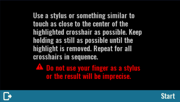
Touchscreen calibration Screen calibration is required to give the firmware the necessary information about its geometry, which will increase the accuracy of data entry.
Initiate this procedure as necessary if you notice that the accuracy of data entry is no longer satisfactory.
New screen calibration can be initiated also by touching the screen anywhere and hold for more then 15 seconds.
SCPI CALibration:SCReen:INIT
|
|
|
For a successful calibration, you have to use stylus or similar rounded tip object and touch the three dots on the screen as accurately as possible.
|

|
|
After successfully defining the three points, a new page will appear where you can choose between saving calibration data, repeating or canceling the calibration.
On the same screen is possible to test precision by touching the surface beyond the options mentioned. |

|
|
Turn display off By turning display off user interaction is no longer possible. To reactivate it, you have to touch and hold anywhere on the display for a short time.
SCPI DISPlay OFF
|
|
|
Test Display test is used to detect defective pixels (aka deal pixels). After the initial message, with each subsequent touch, the entire screen will be painted in primary colors (red, green, blue) following by white. It will be easy to notice if any of the pixels are defective. |
|
|
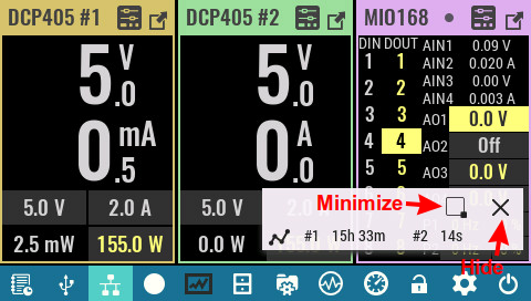
Overlay Determines whether overlay information is displayed or not. When set to Visible then overlay information will have the option to Minimize or Hide. If Hide icon is tap and hold for 3 seconds the overlay menu will dissapear and Overlay state will be changed to Hidden. Here you can make it visible again. When Minimize is selected the icon will change to Maximized and the overlay information will remain visible on the screen in minimized form. |
|
|
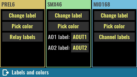
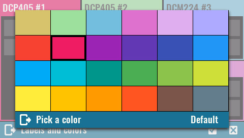
Pick color The header and frame module or resources (as in the case of a DCM module that has two) displayed on the screen will get a default color that can be replaced with one from the 24 color palette.
Once the color has been changed on a new arrival on this page, the Default option will also appear at the bottom in case you want to return to the original color.
SCPI SYSTem:SLOT:COLor {slot}, {color} |
|
|
IMPORTANT: Changes to Labels & Colors depend on the user profile selected. If it is Profile 0 and you want the changes to be visible during the next power up then make sure that the Autorecall on Power-on option is set (see User profiles).
|
|

SCPI
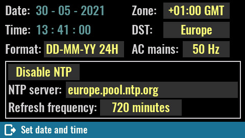
SYSTem:TIME {<hours>}, {<minutes>}, {<seconds>}
Zone
Defines time zone as offset from GMT.
SCPI
SYSTem:TIME:ZONE {<zone>}
DST
Determines Daylight saving time (DST) rules used in your region. The following rules may apply: Europe, USA or Australia.
SCPI
SYSTem:TIME:DST {<rules>}
AC mains
Set the frequency of your AC mains here. This parameter determines the PLC (power line cycle) used for A/D conversion in modules such as MIO168 (default value is 50 Hz).
SCPI
SYSTem:LFRequency <frequency>
Format
Sets one of the possible four combination of date, month, year and 12/24 hour that is used for e.g. displaying datetime of the file when accessing it from the File manager.
SCPI
SYSTem:DATE:FORMat {<format>}
Enable / Disable NTP
Internal clock synchronization with NTP server can be enabled or disabled. When enabled, a NTP server entry field will be displayed.
The NTP communication requires active Ethernet connection.
List of most appropriate and available NTP servers is available at ntppool.org
SCPI
SYSTem:COMMunicate:ENABle {<bool>}, NTP
NTP server
NTP service server network address. The EEZ BB3 will try to establish connection with the selected NTP server on every power up (hard reset), when *RST is issued or once per day.
SCPI
SYSTem:COMMunicate:NTP {<server>}
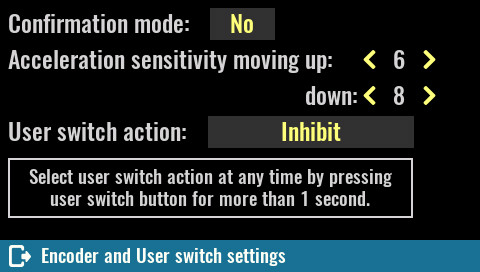
8.14. Encoder & User swConfirmation mode The encoder comes with a tactile switch and if this mode is selected then it will be used to confirm the newly changed value. By definition, the mode is not enabled which means that pressing the switch will instead move the "cursor" to the next editable field.
|
|
|
Acceleration sensitivity moving up/down The rotation speed of the encoder is measured and defines in what steps the selected value will change. The reaction (sensitivity) to increasing the rotation speed in one direction or the other (increasing values or decreasing values) can be set by these parameters.
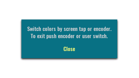
User switch action Opens a menu with functions that can be assigned to the user switch on the front panel. See User SW. |
|
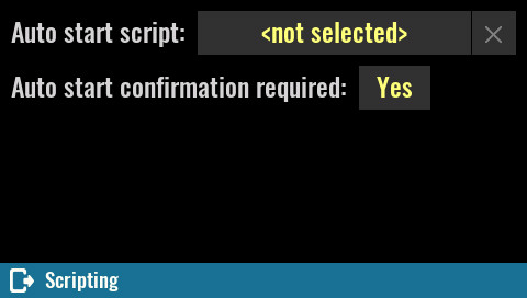
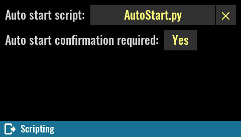
8.15. ScriptingOn this page it is possible to define which MicroPython script will run on the startup.
Auto start script: The name of the MicroPython script to run.
|
|
|
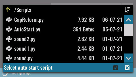
When the name field is selected, the contents of the SD card Scripts folder are displayed by default.
|
|
|
The currently defined script can be replaced with another by tapping the script name. Use the X button to completely remove the auto start script.
Important: the auto start script is saved in the user profile so it is possible to define different startup scenarios. If you change the name of the script, don’t forget to save it in the selected auto recall user profile (if profile 0 is not selected). |
|
|
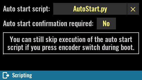
Auto start confirmation required: Use this parameter if you want additional confirmation of running the selected script on the startup.
If No is selected, then it will still be possible to skip the script on startup by pressing the encoder switch during startup (i.e. when the Welcome page is displayed). |
|
|
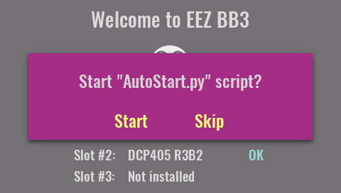
If the Yes option is selected, a dialog box will be displayed during startup.
|
|
|
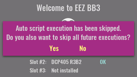
A different dialog box will appear if the No option is selected and the encoder switch is pressed during startup. If yes is selected here, the currently set auto start script will no longer be selected.
|
|
SCPI
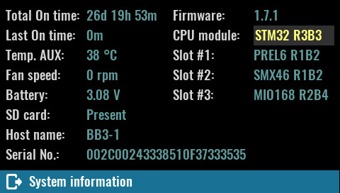
SYSTem:CPU:INFOrmation:ONTime:TOTal?
Last On time
This query returns time passed after last activation of the EEZ BB3. Resolution is 1 minute and this information is stored every 10 minutes in non-volatile memory. Therefore it’s possible that up to 10 minutes is lost after restart caused by a power outage or system reset.
SCPI
SYSTem:CPU:INFOrmation:ONTime:LAST?
Temp. AUX
The "system" temperature is measured on the AUX-PS module and can be used for over-temperature protection (OTP). See System temp & fan.
SCPI
MEASure:TEMPerature? AUX
Fan speed
Current fan speed indicator stated in rpm (revolutions per seconds). Any diagnosed fan faults will be also displayed here. See also System temp & fan.
SCPI
DIAGnostic:FAN?
Battery
Current voltage of the RTC (Real-time-clock) lithium 3 V coin battery (CR2032, Ø20 x 3.2 mm).
SCPI
SYSTem:MEASure?
SD card
Information about presence of mass-storage media (i.e. micro SD card).
SCPI
MMEMory:INFOrmation?
Host name
Local area network (LAN) connection host name.
SCPI
SYSTem:COMMunicate:ETHernet:PORT {<number>}
Serial No
The EEZ BB3 (MCU module) serial number.
SCPI
*IDN?
Firmware
The EEZ BB3 (MCU module) firmware version number.
CPU module
The model name and version of the MCU module.
IMPORTANT: Here you can choose for which version of the MCU module the system firmware will be activated. In case of choosing the wrong version of the module BB3 will not be functional which can be manifested with various problems in communication with peripheral modules. If you are not sure whether the correct version is selected, you can find the version label on the MCU module itself, e.g. r2B4 or r3B3.
If after a reboot you have problems with the r2B4 MCU that you accidentally set to r3B3, check Troubleshooting section.
SCPI
SYSTem:CPU:MODel?
Slot #<n>:
The model name and version of all detected modules.
SCPI
SYSTem:SLOT:MODel? {<slot>}