19. MIO168 mixed I/O module
MIO168 is a versatile module that allows work with various analog and digital signals. The following features are built into the module itself:
- 8 x digital inputs with protections and two voltage levels
- 8 x digital output with protections with low-side switches (Ron = 550 mΩ, max. 550 mA)
- 2 x 12-bit voltage / current bipolar analog outputs
- 2 x 12-bit voltage bipolar analog outputs
- 2 x PWM outputs or power bias for external sensors (±15 V, max. 10 mA)
Additionally, the MIO module has connectors to accept different AFE (Analog front-end) expansion boards depending on the needs for measuring analog signals. The default expansion board is AFE3 which offers the following:
- 4-channel simultaneous 24-bit measurement (effective resolutions up to 18 bit, sampling rate up to 32 KSPS)
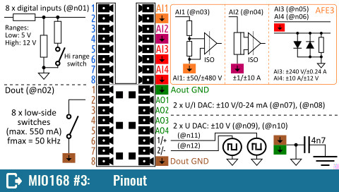
- AIN1: Hi-voltage isolated (floated) input, 2 measurement ranges (±50 V, ±480 V)
- AIN2: Hi-current isolated (floated) input, 2 measurement ranges (±1 A, ±10 A)
- AIN3: Hi-voltage input, 3 measurement ranges (±2.4 V, ±12 V, ±240 V)
- AIN4: Hi-current input, 3 measurement ranges (±24 mA, ±500 mA, ±10 A) share common GND with AIN3
- The current channels (AIN2 and AIN4) are equipped with two fuses: 1.25 A and 10 A.
As in the case of power modules (DCP and DCM) all MIO168 outputs and inputs are galvanically isolated from the main GND (i.e. MCU module), and the above mentioned AIN1 and AIN2 to AFE3 are further isolated from MIO168 GND.
Module user instructions are divided into the following sections:
- Display views
- Digital inputs
- Digital outputs
- Analog inputs
- AC power analysis
- Analog outputs
- PWM generator
- Settings
- Calibration
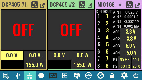
19.1. Display views
|
Unlike power modules that have 5 different display views, there are two available to display MIO168 parameters: Numeric (picture on the right) and Horizontal bar (picture below).
|
|
|
|
|
|
In both views, by default, all resources (channels) are displayed, which gives a good overview of all states. However, interaction with certain channels can be problematic due to limited touch area. If interaction with only one group of resources is desired, then a menu of all available channel groups can be displayed by clicking on the point icon. |
|
|
The image on the right is an example of a display of a group of Analog inputs for Numeric view, and the image below shows what they look like for Horizontal bar view.
|
|
|
|
|
|
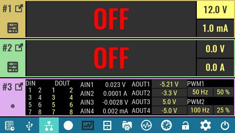
MIO168 module resources can also be displayed in full screen using the maximized icon. When maximized view is selected, navigation arrows to move between modules will be displayed at the top, as well as point icons for quick access to the desired channel group. The first point displays an overview of all resources, and the images that follow will show all channel groups also in a maximized view.
|
|
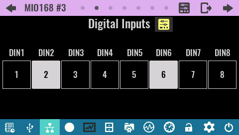
19.2. Digital inputs
|
This page shows the status of all 8 digital inputs at the same time. If the input is in a logical High state it will be highlighted (DIN2 and DIN6 in our example).
SCPI MEASure:DIGital[:BYTE]? SENSe:DLOG:FUNCtion:DIGital[:INPut]? |
|
|
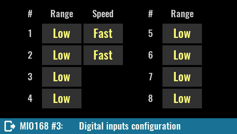
By selecting the Settings icon, a new page appears on which the following can be defined (# indicates the digital input number):
Range The inputs have two voltage ranges:
SCPI SENSe:DIGital:RANGe <pin>, {LOW|HIGH}
|
|
|
Speed Defines the time constant by selecting input capacitance. This only applies to DIN1 and DIN2.
SCPI SENSe:DIGital:SPEed |
|
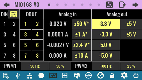
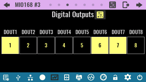
19.3. Digital outputs
Important: digital outputs control low-side switches, i.e. when the output is active it will be connected to GND potential. For this reason, the other end of the load must be connected to the positive rail. Measuring the output voltage without a connected load (or pull-up resistor) will show no change.
|
The digital output page allows you to view and set the status of all 8 outputs. The outputs that are active will be highlighted (DOUT1, DOUT6 and DOUT7 in our example).
SCPI SOURce:DIGital:DATA[:BYTE] {value}
|
|
|
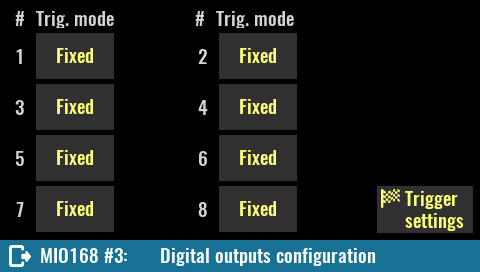
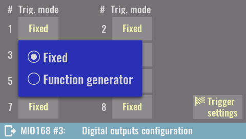
The Settings page offers setting a trigger mode for each individual digital output and displaying general trigger settings (# indicates the digital output number).
|
|
|
Trig. mode
SCPI SOURce:DIGital:MODE {pin}, {FIXed|FUNCgen} |
|
|
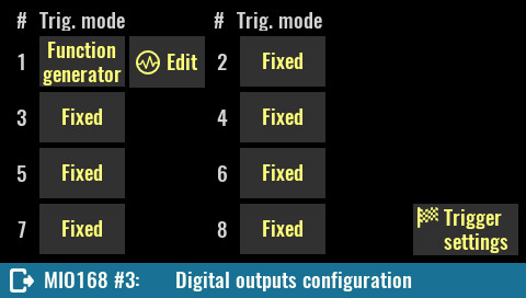
When the Function generator is selected, an additional Edit button will appear which opens the function generator settings.
|
|
|
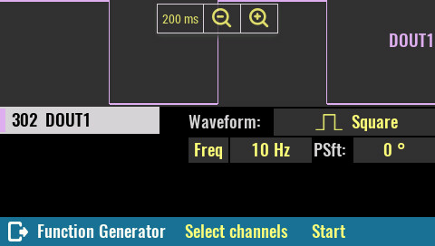
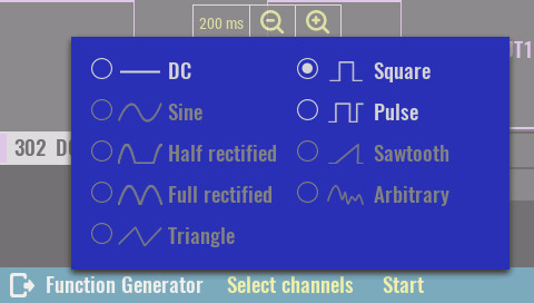
In the function generator settings it will be possible to define Waveform (DC, Square or Pulse), frequency (Freq) and phase shift (PSft).
|
|
|
|
|
|
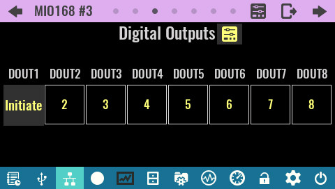
For a digital output that has a Function generator defined as trigger mode, the Initiate text used to start the function generator will appear.
|
|
|
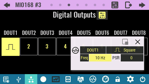
When the function generator is started, the icon on the digital output will change and the overlay menu will appear.
|
|
19.4. Analog inputs
When measuring values at analog inputs, averaging of multiple samples over the time defined with the NPLC parameter is used that can be set independently for each channel.
NPLC is number of power line cycles (e.g. 50 Hz in Europe, 60 Hz in North America). Voltage and current measurement resolution accuracy is reduced by power line induced AC noise. Using NPLC of 1 or greater increases AC noise integration time, and increases measurement resolution and accuracy, however the trade-off is slower measurement rates.
|
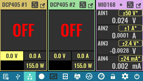
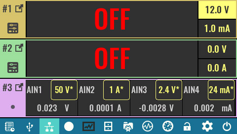
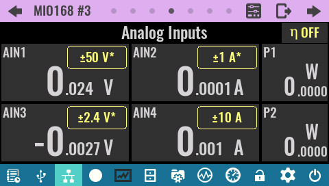
This page displays the analog inputs detected on the installed AFE board. Since AFE3 has voltage (AIN1, AIN3) and current inputs (AIN2, AIN4), the calculated powers are also displayed as P1 = AIN1 * AIN2 and P2 = AIN3 * AIN4.
Pay special attention when measuring power at the AIN3 and AIN4 inputs that share a common GND. The wiring diagram is shown in the description of the AFE3 expansion board. |
|
|
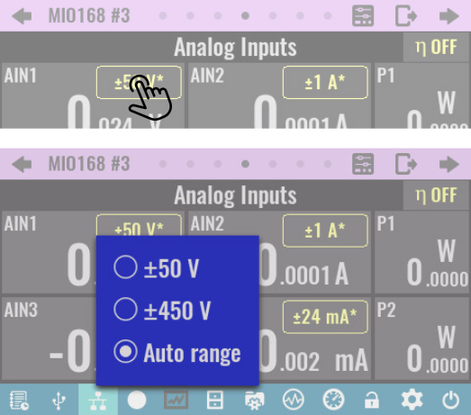
All channels that have multiple ranges have a selection button. If Auto range (software controlled) is selected, the currently selected range will be displayed and marked with an asterisk.
For additional analog input settings, see the Settings section below.
SCPI SENSe:CURRent[:DC]:RANGe {range}, channel SENSe:VOLTage[:DC]:RANGe {range}, channel MEASure[:SCALar][:CURRent][:DC]? MEASure[:SCALar][:VOLTage][:DC]? |
|
|
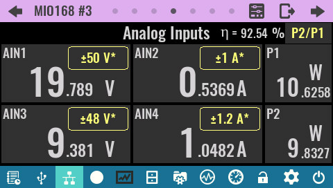
Simultaneous measurement of voltage and current at four analog inputs gives the measurement of two powers (e.g. D.U.T. input and output power) which also allows the calculation of efficiency (η or eta) as a ratio of two powers.
The button in the upper right corner allows toggling between OFF (efficiency is not calculated), P1 / P2 and P2 / P1.
|
|
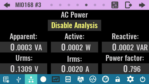
19.5. AC power analysis
|
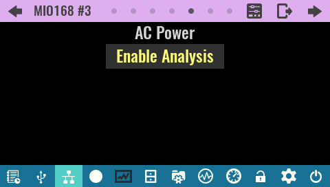
AC power analysis allows the calculation of several useful dynamic values related to the measured voltage and current on the first two analog channels of the AFE3 expansion board (i.e. AIN1 for voltage and AIN2 for current).
When AC power analysis is enabled, the NPLC value is not taken into account (no averaging is done) and sampling is performed with max. speed (32 KSPS). |
|
|
The following values can be measured in real time when AC power analysis is enabled:
|
|
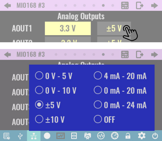
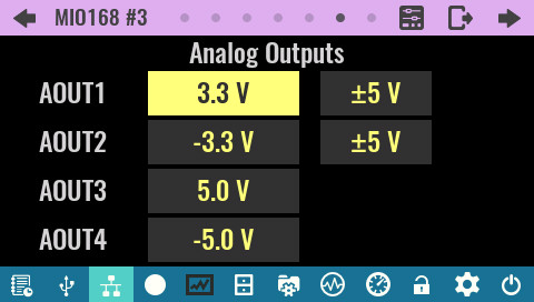
19.6. Analog outputs
|
The analog outputs consist of two sections:
|
|
|
The first two outputs have an additional range selection button.
For additional analog output settings, see the Settings section below.
SCPI SOURce:CURRent[:DC]:RANGe {range} SOURce:VOLTage[:DC]:RANGe {range} |

|
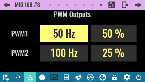
19.7. PWM generation
|
Two PWM outputs allow the generation of a rectangular signal with a defined duty cycle.
SCPI SOURce:PWM:DUTY {duty} SOURce:PWM:FREQuency {frequency}
|
|
|
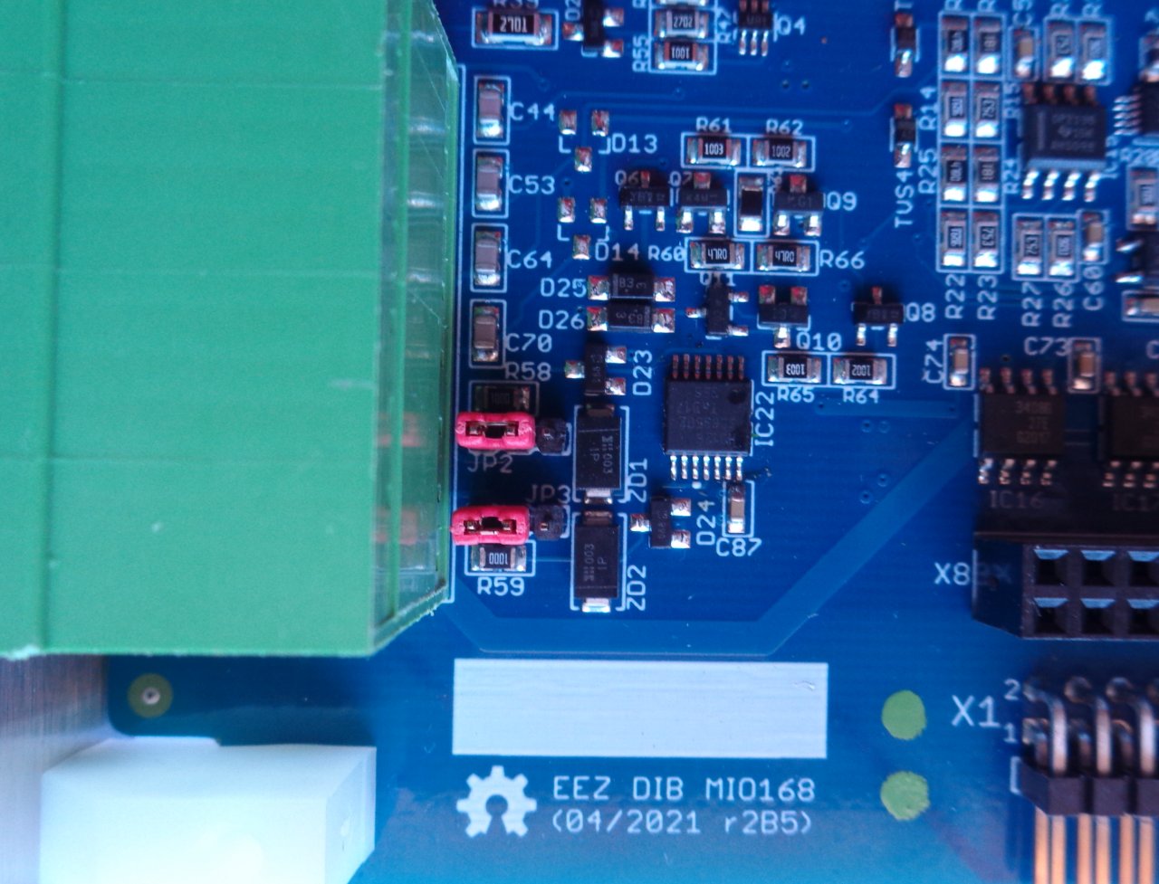
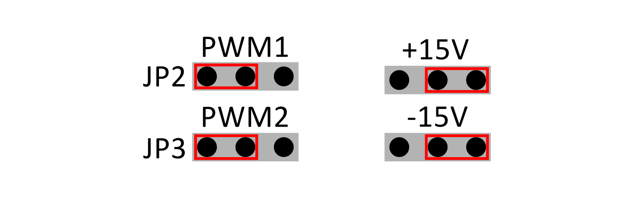
The PWM outputs are functional only if JP2 (for PWM1) and JP3 (for PWM2) are set as in the figure to the right (AFE expansion board removed) which is the factory setting.
|
|
|
If the PWM1 and PWM2 outputs are to be used as a bias power supply (+15 V at PWM1, -15 V at PWM2, max. 10 mA each) for external sensors it will be necessary to change the position of the jumpers. |
|
19.8. Settings
|
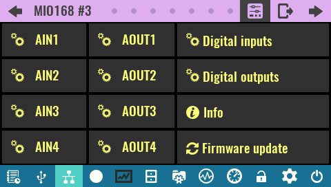
The Settings page allows access to the settings of all types of MIO168 module resources from one place. It is the only way to access all the analog input and output settings listed below. |
|
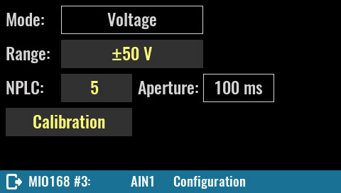
19.8.1. AIN settingsMode: Output mode selection (voltage or current). In the case of an AFE3 expansion board that does not offer two modes, the installed mode is displayed.
Range: Channel range selection.
|
|
|
NPLC: NPLC value for DC measurements. It can be from 0 to 25.
SCPI SENSe:NPLCycles {cycles}
Aperture: The shown aperture value is coupled to NPLCycles by the equation: APERture = NPLCycles / selected AC line frequency. For example, for NPLC of 5 and 50 Hz the integration time is 100 ms and for the same NPLC and 60 Hz the integration time is 83.3 ms. See also Date & time section.
SCPI SENSe:APERture {period}
Calibration Starts the calibration procedure for the selected voltage or current range. If the Auto range is selected, this button will not be displayed. |
|
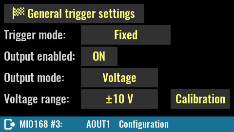
19.8.2. AOUT settingsAnalog output settings in addition to shortcuts to General trigger settings and Calibration, also offers setting the following parameters:
Trigger mode:
SCPI CURRent:MODE {FIXed|FUNCgen} VOLTage:MODE {FIXed|FUNCgen} |
|
|
Output enabled: Defines the state of the analog output (AOUT1 and AOUT2 only).
SCPI OUTPut[:STATe] {ON|OFF}
Output mode: Defines the analog output mode (AOUT1 and AOUT2 only).
Voltage/current range: Voltage range selection. Current range selection only applies to AOUT1 and AOUT2.
SCPI SOURce:CURRent[:DC]:RANGe {range} SOURce:VOLTage[:DC]:RANGe {range} |
|
|
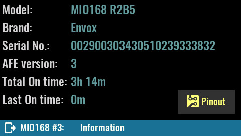
Module information page. The module parameters are displayed as in the case of other module types (see Info section). Specific to the MIO168 module is to display the AFE version. (3 stands for installed AFE3 expansion board). |
|
|
The Pinout image may vary depending on the AFE installed (pinout with AFE3 installed is shown). |
|
19.9. Calibration
Calibration is required for analog outputs (on the MIO168 module) and analog inputs (on the AFE expansion board). The procedure is similar to the power module calibration described in Power modules calibration. Please note that the initial calibration password is eezbb3.
19.9.1. Analog input (AIN) voltage calibration
|
To calibrate the analog input, it will be necessary to connect an external DC voltage source to the input terminals of the AIN channel. An external voltmeter should be connected in parallel. Successful calibration will require two-point measurements. Since AIN channels accept bipolar signal, it is recommended that one measurement be with positive voltage and the other measurement with negative voltage. For a negative voltage it will be necessary to reverse the polarity of the connected external DC voltage source. |

|
Calibration will need to be done for each range of each channel. In the case of AFE3 which has two ranges for AIN1 and AIN2, and three ranges for AIN3 and AIN4 it will be necessary to repeat the procedure 10 times.
The procedure for calibrating the first range (±50 V) of the AIN1 channel is described below as if it were being calibrated for the first time, i.e. as if there were no previous calibration points.
If recalibration is performed, the simplest way is to delete the existing calibration points and follow the described procedure.
|
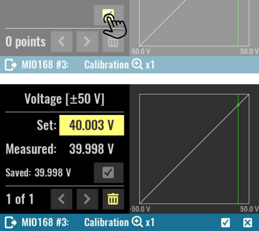
1 |
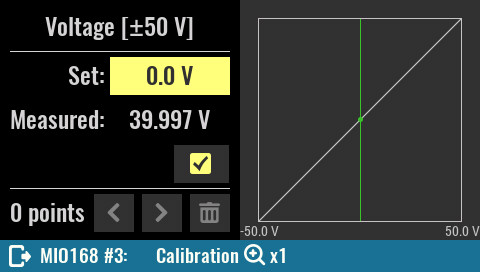
After successfully entering the calibration password, a calibration page will appear showing the selected range to be calibrated.
The number of calibration points is 0. |
|
|
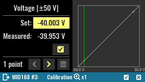
2 |
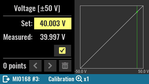
In the Set field, enter the voltage measured by the external DMM (40.003), and the read only Measured field displays the value measured by the AFE (39.997). |
|
|
3 |
Once the Set value for the first point is entered and we are satisfied with the value measured by the AFE, we can save the first point. As a confirmation, the Save button will be disabled and the text Saved: will appear.
The number of calibration points changed from 0 to 1.
If we are not satisfied with the selected calibration point or its measured value, it can use the Delete button. |
|
|
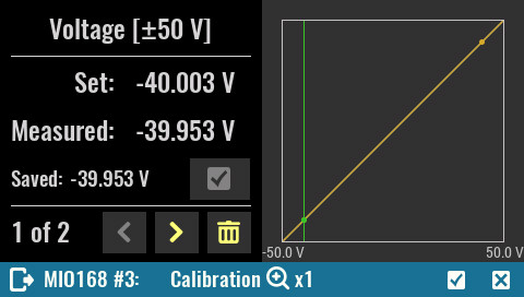
4 |
We can now enter the second calibration point. If we simply reverse the polarity of the DC voltage source, and the external DMM has a negligible so-called turnover error then it is to be expected that the same voltage will be measured as in the previous case only with a different sign (-40.003 in our example). |
|
|
5 |
Use the Save button again to save the second calibration point.
The number of calibration points changed from 1 to 2. |
|
|
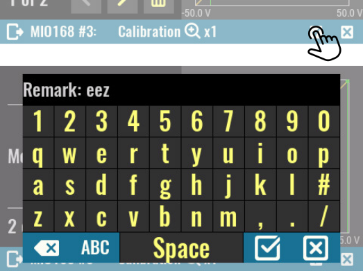
6 |
Once we have successfully added two calibration points, it is possible to complete the calibration and enter a remark (eez in our example).
|
|
|
7 |
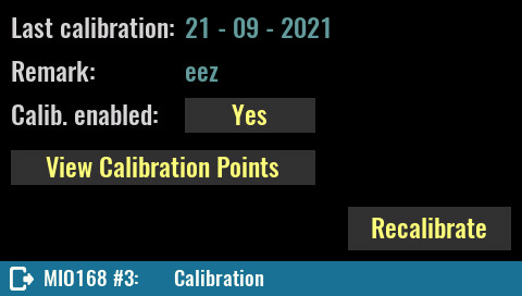
Upon completion of the calibration, a page will appear displaying the date and remark of the last calibration. Here is also possible to disable usage of calibration parameters, display saved calibration points and start recalibration. |
|
19.9.2. Analog input (AIN) current calibration
|
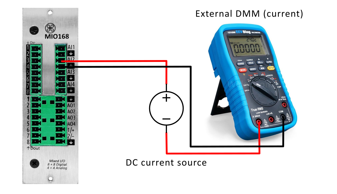
To calibrate the analog current inputs (AIN2 and AIN4 on AFE3) it will be necessary to connect an external DC current source in series with the external ammeter.
The calibration is identical to the procedure described above (steps 1 to 7). |
|
19.9.3. Analog output (AOUT) voltage calibration
|
Voltage calibration of analog outputs will not require an external DC voltage source but only a directly connected external voltmeter.
|

|
|
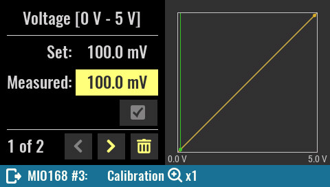
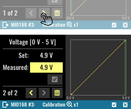
1 |
The calibration of the analog output voltage is similar to the calibration of the analog input with the difference that the calibration points are immediately set to 100 mV For the 0-5 V range calibration example, it will be 0.1 V and 4.9 V. |
|
|
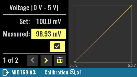
2 |
After entering the value measured by the external voltmeter (98.93 mV) we can save the calibration point using the Save button. |
|
|
3 |
To move to the second calibration point you will need to click on the right arrow button. |
|
|
4 |
Enter the measured value with the external voltmeter (4.899). |
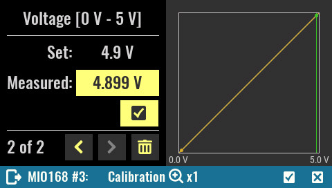
|
|
5 |
Once the second calibration point has been saved, it is possible to complete the calibration by selecting the confirmation button. |
|
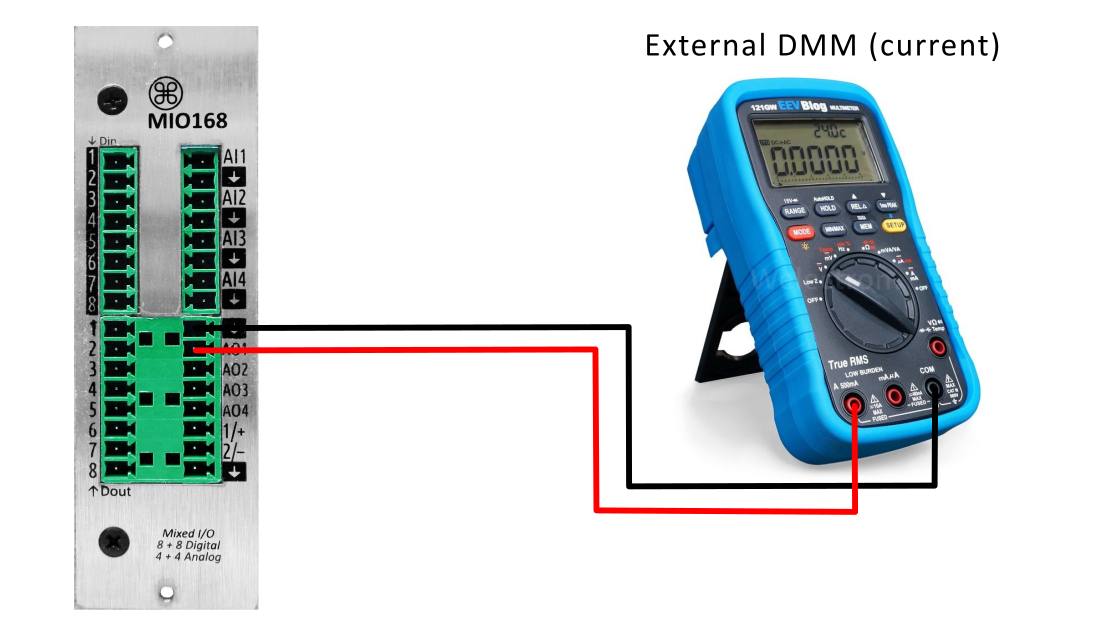
19.9.4. Analog output (AOUT) current calibration
|
Current calibration of analog outputs (AOUT1 and AOUT2 only) will not require an external DC current source but only a directly connected external ammeter.
The calibration is identical to the procedure described above (steps 1 to 5).
|
|