Auxiliary power (AUX PS) module
|
Current version |
r5B13 |
|
Status |
Completed, ready for production |
|
PCB manufactured |
Yes (r5B12) |
|
PCB assembled |
Yes (r5B12) |
|
BOM |
Yes (Farnell, TME, Digikey, Mouser, RS) |
|
File repository |
https://github.com/eez-open/psu-hw/tree/master/Aux%20power |
|
License |
|
|
Contributions |
|
|
Revision history |
2017-09-24: r5B13
2017-03-24: r5B12a (Version 3.0 on GitHub)
2017-10-11: r5B11
2016-10-24: r5B10 2016-07-24: r5B9 (Version 2.0 on GitHub)
2016-06-14: r5B8
2016-05-26: r4B43 (Version 1.0 on GitHub)
2016-05-01: r4B42
2016-04-06 r4B41
2016-01-27 r4B40
2015-11-14 r4B39 – First public release |
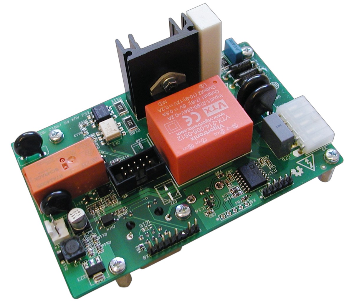
Fig. 1: AUX PS module assembled (PCB r5B12)
The Auxiliary power module contains the following circuits:
- AC power input protection,
- In-rush current limitation and standby circuit for main transformer or AC/DC power modules,
- Dual output AC/DC module for powering the Arduino shield module (+5 V) and cooling fan (+12 V),
- DC fan controller
- Ethernet and USB connectors are made available on the enclosure’s rear panel and
- digitally controlled power relay (DOUT2)
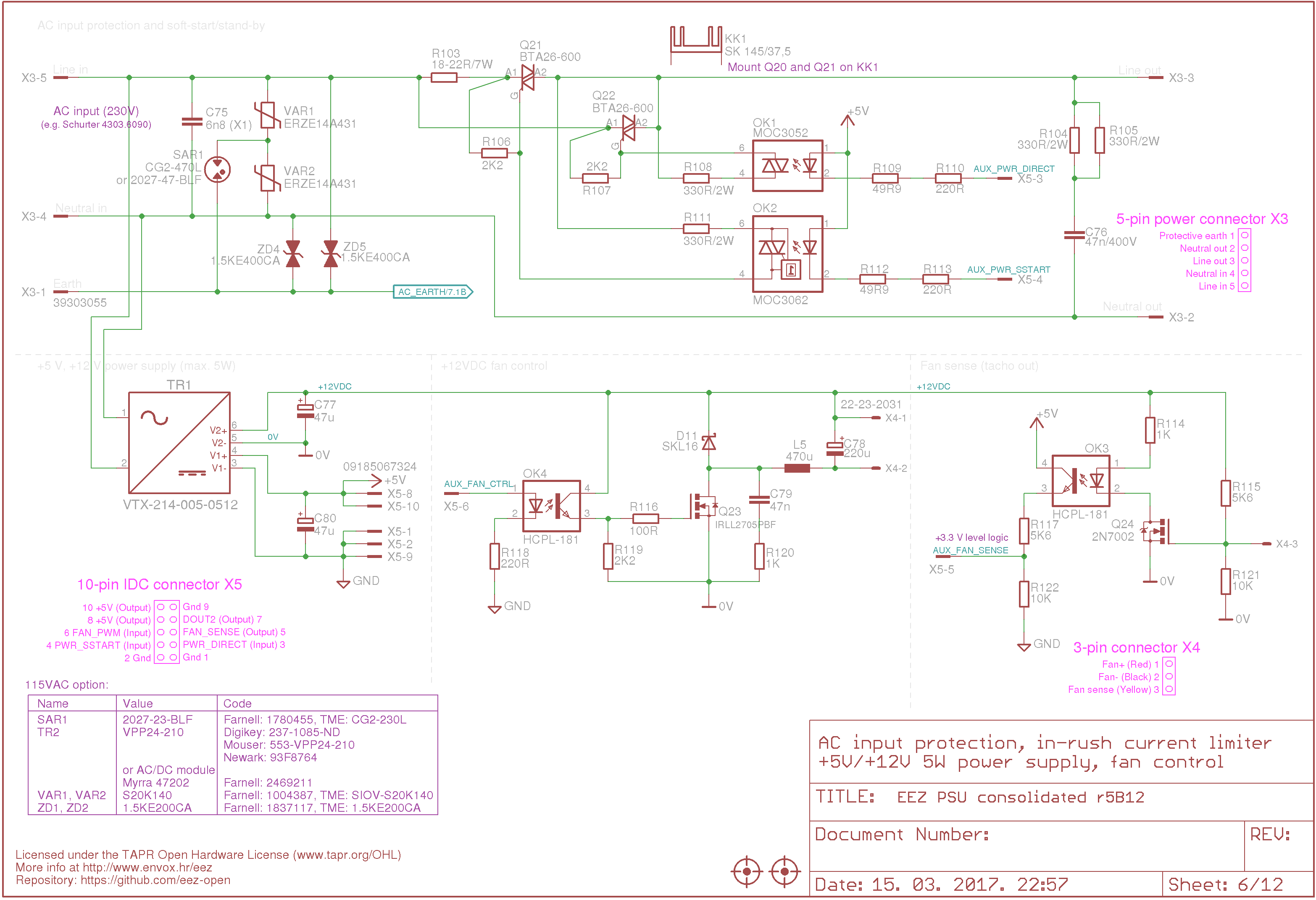
Fig. 2: AC input, soft start and dual output power supply
AC input protection and soft-start circuit
The auxiliary power module is currently the only one that is in direct connection with AC mains voltage.
WARNING: special caution is required when this module is operating.
The AC input line protection is consists of bidirectional TVSs, MOVs and a SAR. That improves immunity against various spikes and disturbances that can appear on mains wiring. They are specified for 230 VAC and could be modified for better sensitivity if the PSU is to be connected to 115 VAC mains voltages. Between this module and the AC mains a fused IEC inlet is needed (optionally, replaceable with built-in or separate AC switch and EMI filter).
The in-rush current limiter provides soft-start of the mains power source, especially if a toroidal transformer is used; toroids are notorious for drawing very high currents until its core becomes magnetized. If AC/DC power modules are used instead of a transformer, this limiter provides an even smoother power-on by supplementing the effect of the in-rush limiter that is usually installed in such items. In-rush current limitation is done with a power resistor (R103, Fig. 2) in serial with the load (transformer or AC/DC modules) at the beginning of the power-up sequence. When the power-up current in-rush peaks (typically within 100 ms, Fig. 3 magenta trace) is finished, we can disconnect R103 to avoid further heating it and eventual permanent damage. Connection of R103 is managed by the MCU that controls triac Q21 with PWR_SSTART signal (Fig. 3 cyan trace). Shortly after the input current settles down, an additional circuit in parallel with that one is established by firing Q22 using PWR_DIRECT signal (Fig. 3 blue trace). Finally, the former circuit with R103 is disconnected and AC mains power-up sequence is completed.
Note that Q21 and Q22 are controlled with two different type of opto-triac: the first a Zero-crossing type and the second a nonzero-crossing (or random) device. That means that power-up sequence can only start when the mains voltage is minimal (zero); R103 bypassing can happen at any time after the transformer’s core is magnetized.
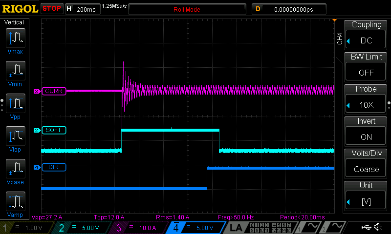
Fig. 3: Mains transformer line in-rush current on power up with active soft-start
Obviously, the circuits discussed above regarding power-up, can also be used for power-down or Standby action. That can be done by simply pushing the PWR_DIRECT signal low, or by removing power from the MCU. Because in the former case the standby switch (SW1, see Fig. 4) on the Arduino Shield does not need to carry high voltages nor dangerous AC mains currents there are no dangerously high voltages present on the Arduino Shield (or the front panel).
Dual output AC/DC module
The PCB mounted 5 W AC/DC module is used to separately supply the Arduino Shield board and the cooling fan. The two power outputs are isolated (i.e. no common ground exists) partly as a means of suppressing EMI generated by fan. Due to that interfacing, the fan are also isolated using two optocouplers (OK3, OK4).
10-pin IDC connector (X5) is used to power the Arduino Shield board as well as for interfacing with the cooling fan, soft-start circuits, and power relay DOUT2.
Fan speed control
When the PSU works continuously with high output currents, additional cooling is required and an external Ø60 mm DC fan is provided for that case. Powering the cooling fan is regulated by the MCU using the isolated AUX_FAN_CTRL line that is programmed to generate a PWM signal that can be used to adjust output power using Q23 (hence changing the fan speed) without excessive power loss like in case of linear regulation. To decrease spikes coming from the fan which could have negative effects on Q23 and EMI, a few additional parts are added (reverse polarized D11, RC snubber R120, C79 and LC filter L5, C78).
Fan sense
The specified cooling fan has a 3-wire interface; two are used for power and the third for a tachometer (tach) output. It’s forwarded to AUX_FAN_SENSE MCU input (via Q24, OK3) with level shifting to 3.3 V (R117, R122).
The tach output generates a rectangular waveform (it’s a 50% duty cycle, with 2 pulses corresponding to one fan shaft revolution) when the fan is powered from a DC source. But PWM is not a DC source and the tach signal is chopped by the PWM drive signal, since power is not always applied to the fan. The lower the speed the higher the distortion and it becomes completely unusable pretty fast. The Fig. 4 shows signal distortion when speed is decreased by only 10% from the nominal value of 4500 rpm.
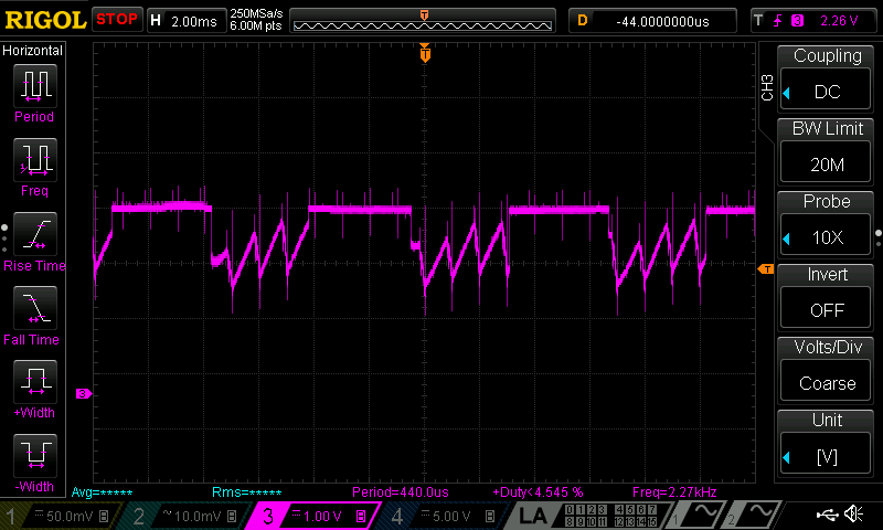
Fig. 4: PWM powered fan tach output (4050 rpm, timebase: 2 ms)
Fortunately, that issue can be efficiently resolved with so-called “pulse stretching” – switching the fan on (i.e. PWM=255, for 8-bit drive) long enough to gather the tach information properly. That can increase audible noise if the on period lasts too long. On the other side, if its too short for the expected frequency range, the results returned from the tach sensor will be inaccurate. On Fig. 5, we show correct tach output waveform for a duration of 25 ms when DC power is applied.
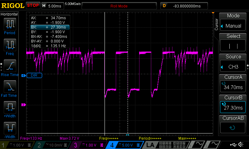
Fig. 5: Fan tach output with "pulse stretching" (4050 rpm, timebase: 5 ms)
Ethernet and USB connections
This module is intended to be mounted directly on the inner side of enclosure’s rear panel. In that way Ethernet (X7) and USB (X11) connector could be directly mounted on the PCB to simplify the cabling. In this way is also possible to mount optional line protection devices close to the place where cables enters the enclosure. Ethernet connection to the Arduino shield is provided via X8 while for the isolated USB connection (IC17) with the Arduino board a X10 is used.
The distance between rear panel and PCB is established with five 14 mm M3 metal spacers that provide good mechanical strength while external cables are plugged in and out.
Digitally controlled power relay (DOUT2)
The AUX PS module has one MCU controlled (via Q25) power relay with both NO and NC contacts accesible from the enclosure’s rear panel (X6). Both contacts are MOV protected; no RC snubber is provided. A snubber might be benefical for working with AC loads; but if needed it will have to be supplied externally.
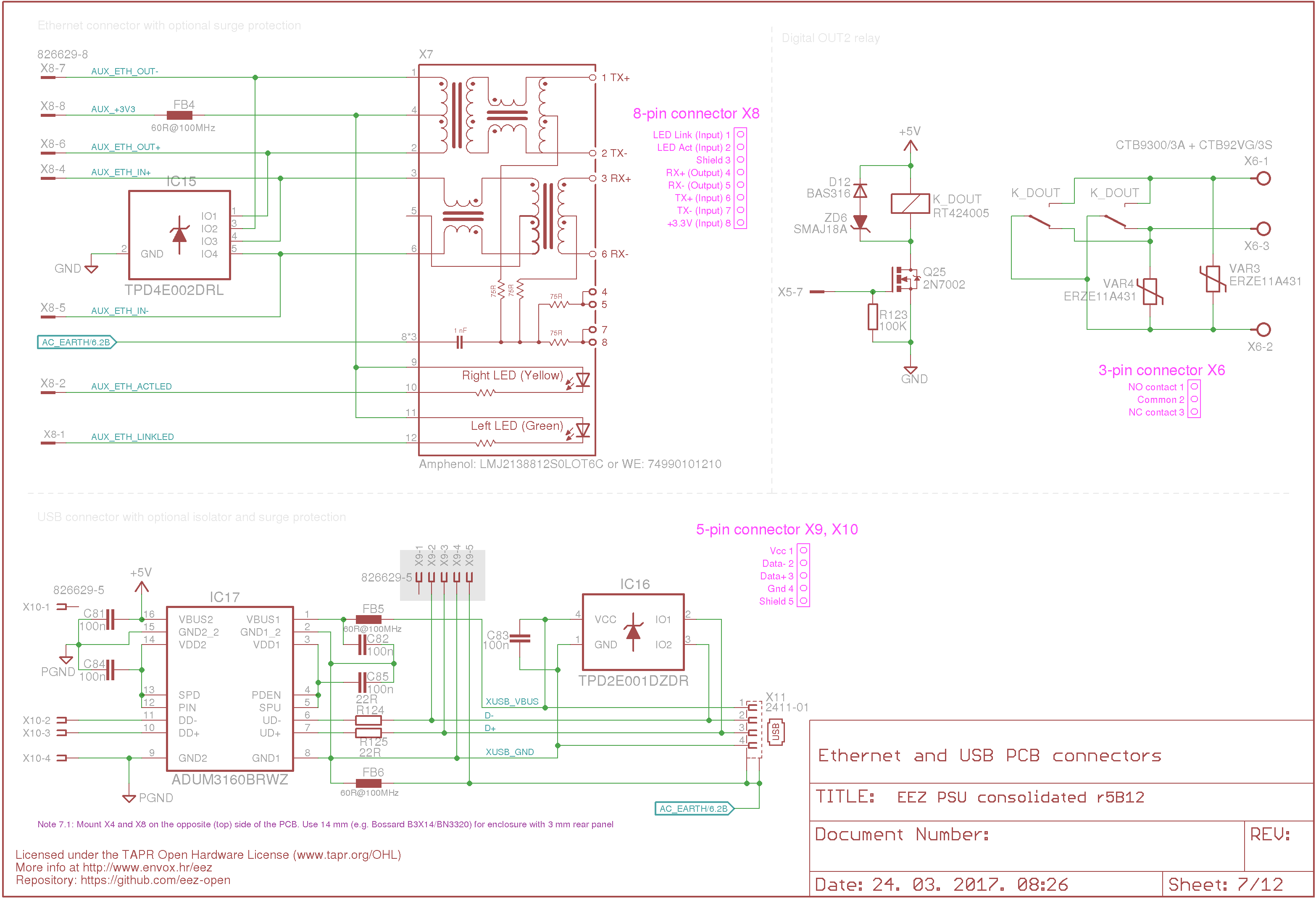
Fig. 6: Ethernet modular jack, isolated USB and DOUT2 power relay
PCB layout
The auxiliary power module is assembled on the 115 x 74 mm two-layer PCB designed in Eagle without autorouter assistance. There are a few places on the PCB that deserve special mention:
- proper spacing between the opto-triac’s low and high-voltage sections,
- adequate (and sufficiently adequate to be safe!) AC power traces width and spacing and
- no trace routed on the top side in the KK1 heatsink area.
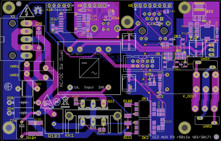
Fig. 7: PCB layout r5B12a (both sides)
SPICE models