Technology overview
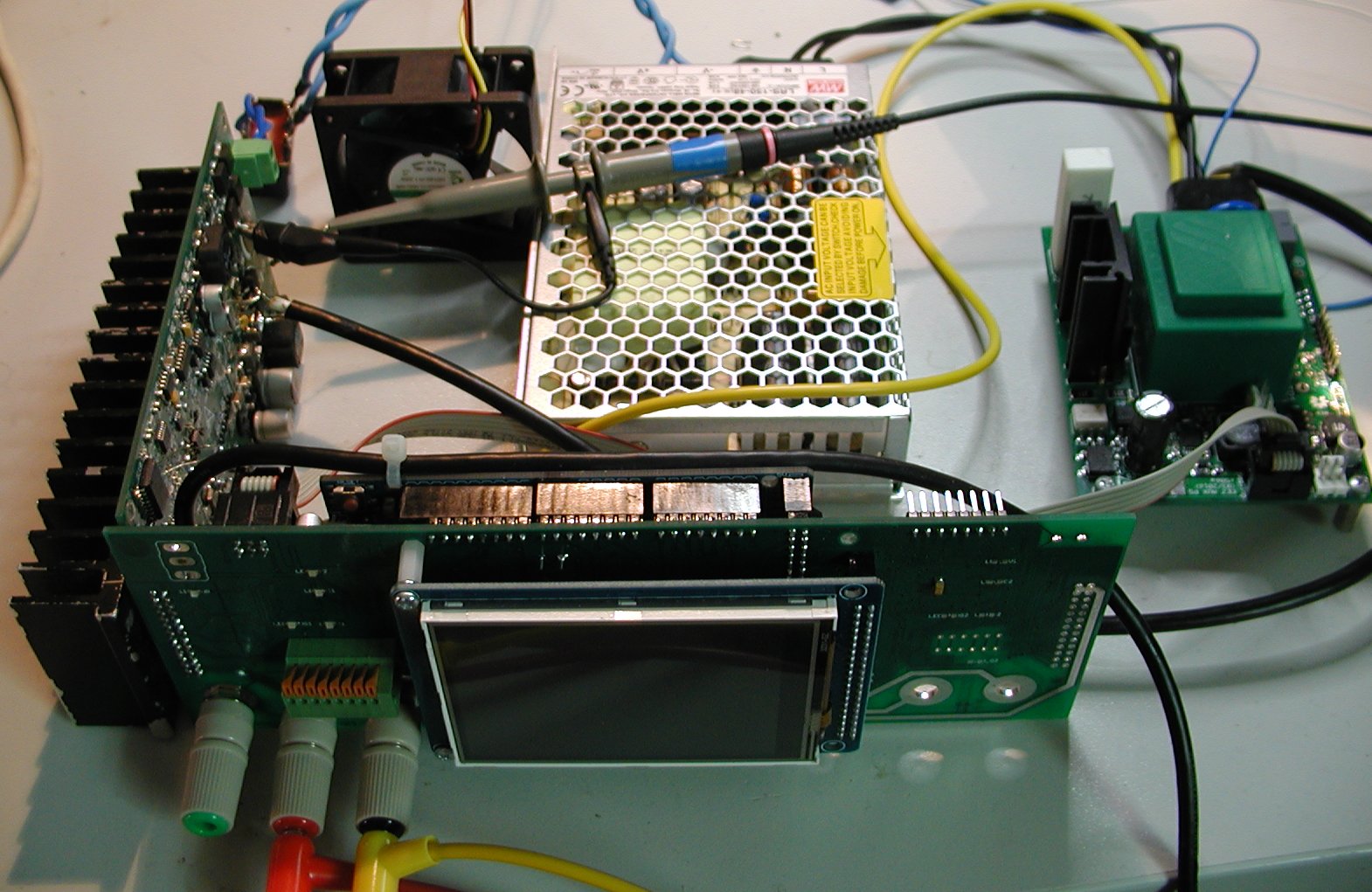
Fig. 1: EEZ PSU early prototype
This programmable bench power supply (PSU) was designed taking into consideration the following mixture of goals and requirements:
- Modular design allowing a combination of modules with various performance and capability and creation of multiple output solution (e.g. a minimum of two channels)
- A single input for both internal power and bias supplies, removing any need for a custom multiple secondary winding main transformer
- SMPS (switch mode power supply) pre-regulator circuit for lower power dissipation
- SMPS pre-regulator "100% Duty cycle" operational mode to reduce ripple and noise on the PSU’s output
- A TFT color touch-screen as an input control device, and a display output for perfomance information
- Microcontroller (MCU) managed serial and parallel connection for combining PSU channel outputs if suitable
- Voltage limit regulation (CV) with 1/10 mV resolution, up to 50 V (default: 0 – 40 V)
- Current limit regulation (CC) with 0.1/1 mA resolution (when dual range operation, default: 0 – 500 mA / 0 – 5 A)
- Minimal overshoot when a new voltage or current level is programmed, or for cases at the margin, such as power on/off
- A minimum of 15-bit resolution for data acquisition for controlling the PSU
- Multiple protection mechanisms, for both the PSU itself and for devices it powers: over-voltage (OVP), over-current (OCP), over-power (OPP), over-temperature (OTP), and automatic current limiting when faults in temperature sensors or the cooling fan are detected
- Switching frequency synchronization between switching regulators
- Output enable (OE) circuit, allowing instant (as nearly as possible) output disconnection
- Remote voltage sensing, i.e. Kelvin wiring
- Remote voltage programming (external) “analog” signal control
- External digital trigger signal (3.3 or 5 V logic level)
- Conventional AC input protection for the entire PSU (surge and transient protection)
- Selectable 115/230 VAC with solid-state (not mechanical!) soft-start/standby circuit
- Simple DC output protection (reverse voltage, over-voltage)
- Serial and parallel, firmware controlled, connection of two power output channels
- An MCU based digital control module using 32-bit Arduino/Genuino boards such as the Due
- An SPI bus for peripheral communication
- Galvanic isolation between the digital control circuitry and the power channels
- A real-time clock (RTC) with supercap/battery backup
- An EEPROM for configuration and calibration parameter storage
- Provisions for an SD-card as an additional storage
- USB support for remote control, as a debug console, and for firmware upload
- Ethernet support for remote control
- Fan speed control to reduce operational noise
- An incremental encoder with tactile switch as an additional means of setting output values
- Use of easy to find components readily available from suppliers such as Farnell element14, TMU.eu, DigiKey, Mouser, RS online, etc.
- Possibility to house at least two channels in an affordable and compact (2U height) metallic enclosure
- Comprehensive software support including SCPI remote control, GUI configuration and monitoring, and even a cross platform (Windows, Linux, OS X) PSU function software simulator
Despite the complexity of the proposed design, it should easily possible for DIY assembly needing only intermediate soldering skills for SMD components. The PCB (both Eagle and Gerber files) for PCB production are available on GitHub. Arrangements have been made to offer PCBs directly from suppliers, e.g. OSHpark.
Upload of revised firmware will require only novice programming skills and some familiarity with the Arduino IDE. Short video illustrating download and installation of firmware revisons have been made available.
The PSU building blocks and default configuration
The power supply’s modular design allows freedom to build a flexible, and functional, device. The following modules is possible to use for PSU building:
- Auxiliary power module,
- Power board (one per channel), and
- Arduino Shield (digital control)
Each module is described in more detail below. The default configuration has been named EEZ H24005, and will come with the following features:
- Two “floating” channel with programmable output voltage range 0 – 40 V and current 0 – 5 A (max. 155 W per channel) or 0 – 80 V and 0 – 10 A with MCU managed connection in series or parallel
- Remote voltage sensing (with inverse polarity protection), remote voltage programming
- External digital trigger input, external temperature sensor
- Temperature controlled cooling fan
- AC mains power supplied to two AC/DC power modules (48 Vdc, 155 W)
- Arduino Due based digital control
- 3.2” TFT color touch-screen for local console and operating condition display
- Ethernet and USB for remote control (USB is used for firmware update)
- Metal enclosure: 80 (H) x 290 (W) x 240 (D without handles) mm
Functional block diagram
The block diagram of the PSU is shown below. It includes four modules. The auxiliary power module is used, among other things, for autonomous power of the Arduino Shield board. Complete control of all functionality is performed using the local TFT display touch screen. In addition, the Arduino Shield enables fully featured remote control using serial (via USB) or Ethernet communication.
The remote control is based on a command set that complies with the SCPI 1999.0 specification which is the de facto standard for middle and high-end commercial power supplies, and many other laboratory instruments.
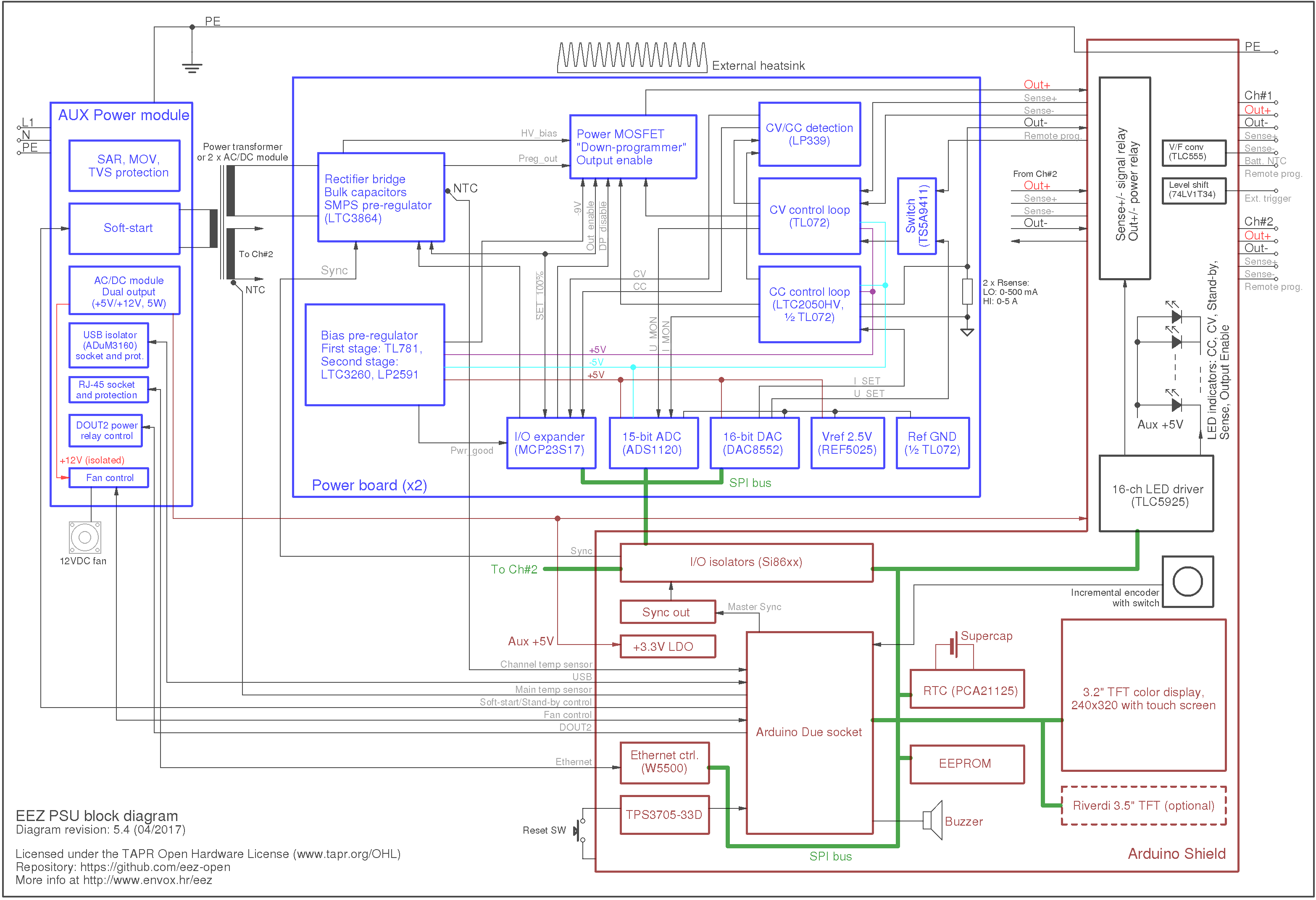
Fig. 2: EEZ PSU functional block diagram
MCU control
The PSU comes with comprehensive set of features that are available locally over the TFT touch-screen display and remotely using the SCPI protocol (via USB or Ethernet port). A unique feature of this project is its firmware simulator that is available as both desktop and web application and enables one to check all built functionalities without having on hand a physical device.
Module description
More information about modules used for building the PSU can be found in the following chapters. A header section with information about module development status has been added to each chapter to simplify progress tracking, like:
|
Current version |
r4B39 |
|
Status |
Completed, ready for production |
|
PCB manufactured |
Yes |
|
PCB assembled |
Yes |
|
Yes (Farnell, TME) |
|
|
File repository |
https://github.com/eez-open/psu-hw/tree/master/Aux%20power |
Schematics